Being able to rinse out glasses at a homebrew event is a big deal. Not only does it mean that your beer will be showcased in its purest form, but drinkers also appreciate getting their sample glasses cleaned out. It elevates the whole experience. So, naturally, as I was preparing to bring some beer to my next homebrew event, I wanted an elegant solution for rinsing glasses—something better than a pitcher of water or a spray bottle. After scouring the Internet for ideas (and not finding many), I settled on this clever bucket idea for a portable glass rinser. The basic concept is to use a 5 gallon keg of water to rinse glasses, with the waste water flowing into a 5 gallon bucket: a self-contained system.
Parts
To build this portable glass rinser, I used the following parts:
I already had a spare ball lock disconnect, so I didn’t need to purchase one for this project. The rest of the parts cost the following for me at the time of purchase, not including tax or shipping:
$4.98 for the bucket
$2.28 for the bucket lid
$8.99 for the glass rinser
$11.34 for the ice maker supply line
$8.88 for the 1/2″ FIP x 1/4″ compression adapter
$3.88 for the 1/4″ compression x 1/4″ FFL adapter
$5.99 for the ball lock disconnect (if needed)
Grand total: $46.34
Build
This build was pretty quick and straightforward. Besides assembly, the only real “build” part is modifying the Lowe’s bucket lid. After placing the glass rinser base on top of the lid to determine where to mount it, I drilled a 7/8″ hole for the glass rinser shank. Then I drilled a 5/8″ hole for the ice maker supply line to pass through. Finally, I cut out a circle in the center of the lid for the lip of the glass rinser to rest and drain into the bucket.
Holes drilled and cut in the bucket lid
After that, it was just assembly: installing the 1/2″ FIP x 1/4″ compression adapter onto the glass rinser shank, the ice maker supply line onto the adapter, the 1/4″ compression x 1/4″ female flare adapter onto the ice maker supply line, and a ball lock liquid out disconnect onto the flare adapter.
1/2″ FIP x 1/4″ compression adapter and ice maker supply line installed on the glass rinser shank
Finally, the supply line was fed through the smallest hole in the lid, and the lid installed onto the bucket.
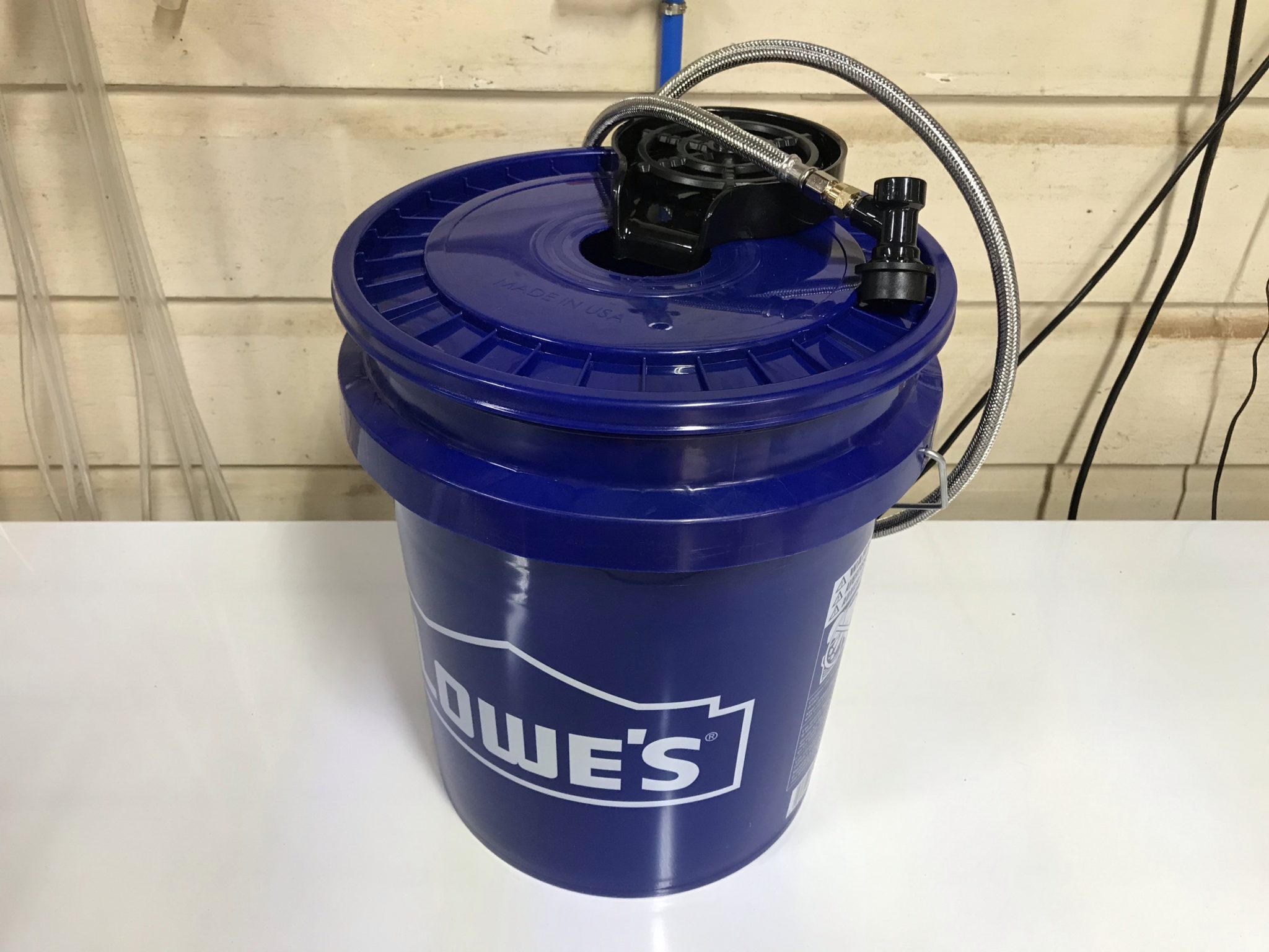
The fully assembled portable glass rinser
To use it, simply attach the liquid out disconnect to a Corny keg full of water, and use 10-15 psi of CO2 to push water to the glass rinser. The water doesn’t need to be kept as cold as beer for rinsing, so the whole setup can be easily toted around as needed without the need for a jockey box, ice, or even a table. May your patrons enjoy clean glasses at your next event!
Testing the portable glass rinser using the water keg in my keezer
After moving a few years ago and selling my fermentation chamber, I’ve been without proper temperature control for my beers. I’ve been fermenting them in the house—typically in the bathroom, which stays a bit warmer than the rest of the house. When the “shower beer” situation peaked at 25 gallons of beer, I realized I need to solve this problem sooner than later: I needed a way to ferment in the garage and control temperature. Time to build a DIY glycol chiller!
Too much shower beer!
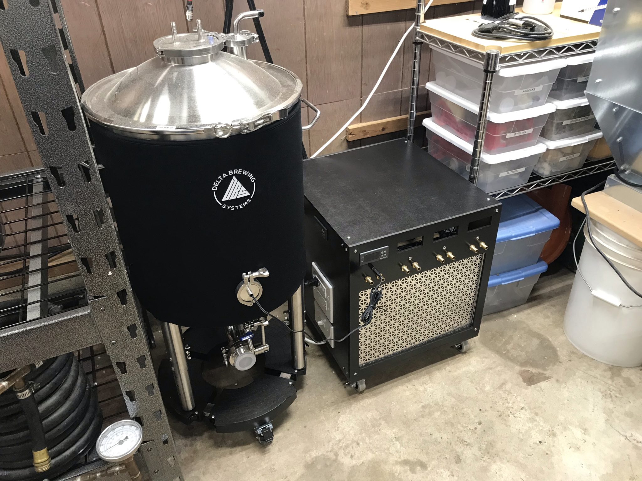
Whereas I had previously built a fermentation chamber to control temperature via heating and cooling the air, this time, I decided to step up my game and move into glycol chilling. This would require fermentors capable of supporting a chilling coil, as well as the glycol chiller and circulation system. After some research, I settled on the Delta FermTank 14 gallon fermentor.
For the chiller, I stuck to my guns and went the DIY glycol chiller route using a window A/C unit and a cooler. But not wanting to be outdone, I over-engineered this thing to be more compact than the other DIY solutions I’d seen.
Parts
Midea 5000 BTU mechanical window air conditioner (Walmart)
The first step was to cannibalize the A/C unit. I set the temperature and mode to maximum cooling capacity, then removed the knobs and exterior case.
The A/C with front panel removedThe A/C with enclosure and evaporator fan removed
Then I went about slowly and carefully realigning the evaporator coil to fit into the cooler.
The scariest part of this whole build: reorienting the evaporator coil
Bypassing the thermostat
To make the A/C run whenever the temperature controller told it to, I had to bypass the built-in thermostat. I did this by folding up the probe inside the wiring enclosure, then wiring the two leads from the thermostat control to each other, bypassing the control completely. The thermostat could be removed completely, but since it wouldn’t save me any space in the overall build, I left it where it was.
The bypassed thermostat
Closing the gap
I used a hacksaw to remove the excess shaft coming from the fan motor to save space. I also made several modifications to the metal base plate of the A/C unit to facilitate placement of the cooler. If I were to do this again, I might just remove the base plate entirely and make my own mounts for the compressor, fan, and wiring enclosure.
The shortened fan motor shaftModifying the base plate with a hacksaw
To fit the cooler as close as possible, I also modified the wiring enclosure so the start capacitor could be reoriented 90º. This took a bit of cutting with tin snips and adding screw holes, but wasn’t too difficult.
The rotated A/C capacitor
I shopped around for the smallest cooler I could find that would fit the coil. This would minimize both the amount of glycol needed and the chilling time. With the modifications to the A/C base plate, wiring enclosure, and fan motor shaft, I was able to snug the cooler up very closely in the A/C footprint.
A test fit of the cooler with preliminary wiring mockup
Wiring the chiller
The wiring for this DIY glycol chiller was a bit of an evolution. I wanted to keep it as flexible as possible while using easy-to-get components. I initially started out with house wiring components, but ended up using a combination of house wiring and stranded project wiring. To handle the majority of the wiring within the enclosure, I bought a spool of 14-gauge stranded wire and several terminal blocks.
The end result is a chiller with a light switch as the main power switch, standard outlets for powering external heaters for each fermentor, and internal terminal block wiring for running the A/C unit, glycol circulation pump, exhaust fan, and each fermentor’s pump, as well as all the temperature controllers.
For components like the circulation pump that had standard power cords, I trimmed the plug off and crimped on spade terminals to connect them directly to the terminal blocks. For components like each fermentor’s glycol pump that have a wall wart, I modified cheap extension cords in a similar manner, so the power adapter plugs into the extension cord, and the extension cord is wired directly to the terminal block.
The terminal block wiring and modified power cords
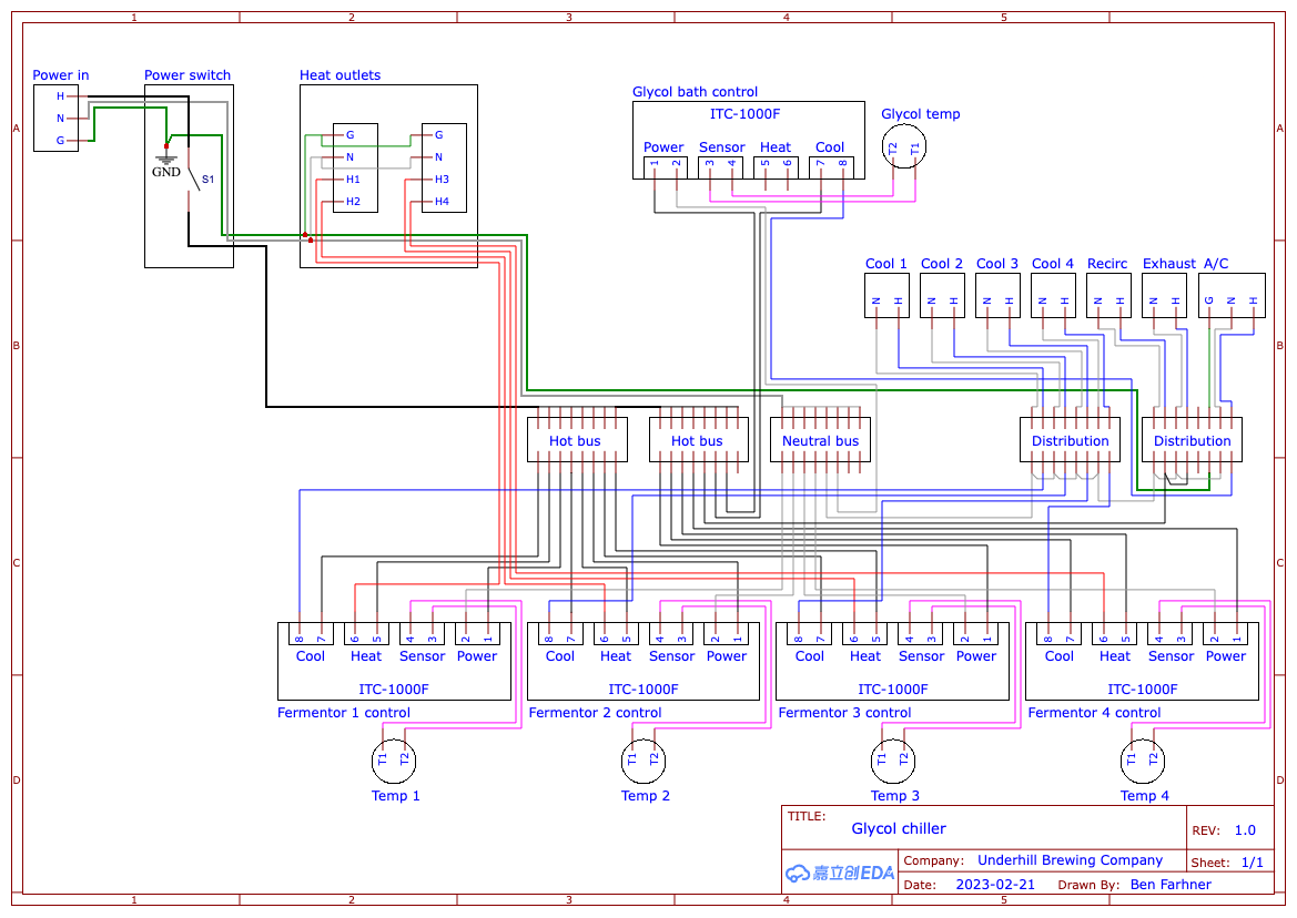
This is the final wiring diagram I arrived at after a few iterations and simplifying things as much as possible:
The final wiring diagram
Building the Enclosure
I originally started building the enclosure from 3/4″ plywood that I had on hand, but quickly realized I needed something thinner to be able to panel-mount the components. I also wanted something that could be more easily removed for service. In the end, I used fiberboard panels mounted to aluminum angle brackets on a plywood base.
Original plywood enclosureNew and improved fiberboard enclosure on casters
I designed the chiller to be able to support a total of 4 fermentors. I only have 1 right now, so I haven’t verified that it’ll work at that capacity, but as I expand I’ll be able to test it out. If it can’t handle 4 a time, I could modify the build and enclosure as necessary.
Since the temperature controllers support both heating and cooling, I designed this system with outlets for heaters. Each outlet is controlled separately, so each fermentor’s heating jacket can be plugged in constantly and only receive power when it needs to raise the temperature.
The side of the chiller, featuring the power switch, heating outlets, and glycol bath temperature control
With the initial assembly of the enclosure, I realized there wasn’t enough airflow inside when the A/C was running. In fact, this led to the A/C fan motor overheating and melting its plastic mount! Fortunately, I was able to salvage it without any major impact to function. To solve the airflow issue, I added an exhaust fan that runs constantly, even with the A/C off. I also added a vent hole in the bottom of the enclosure to allow fresh air in.
The exhaust fan for ventilation inside the glycol chiller
Now that I no longer have my fermentation chamber, I needed a new temperature controller to control a fridge for fermentation or serving.
I wanted something that would match my brewery control panel, so I went a little above and beyond on this build, but I’m really happy with the results.
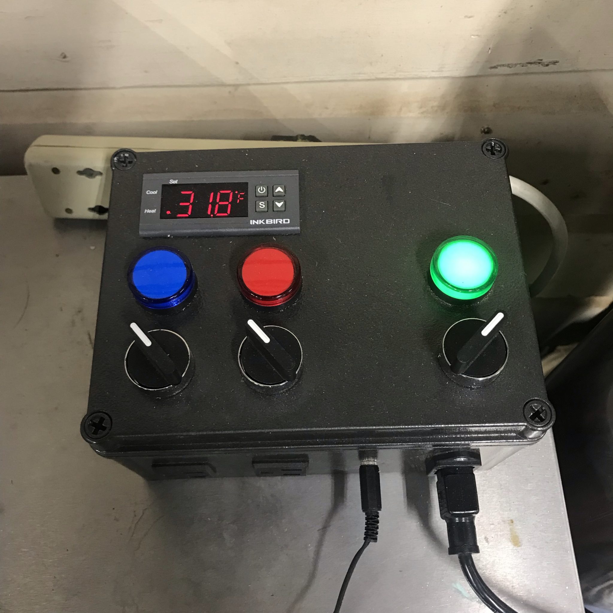
Completed temperature controller, monitoring fridge temperature
(1) Panel mount 1/8″ (3.5 mm) TS or TRS jack (Amazon)
14 ga wire
Build
First, I prepped the project box by drilling holes for the 22 mm indicators and switches using a 7/8″ Forstner bit. The hole for the 1/8″ jack was drilled with a 1/4″ Forstner bit.
For the square holes, I found the easiest way was the drill a hole in the corner, saw from the holes to the other corners with a hacksaw, then score the sides and bend them in the break them out. I cleaned up the edges with a utility knife.
Once all the mounting holes were cut, I did a test fit to make sure it all fit correctly.
Then I removed everything, scuffed up the project box with some 150 grit sandpaper, and spray painted it with the same Rustoleum black hammered finish paint that I used for the brewery control panel.
Wiring
I used 14 ga house wiring for everything inside the box except the sensor wires, for which I used smaller 18 ga wires that I had left over from a ceiling fan.
I used wire nuts for all the junctions but it would look a lot cleaner with terminal blocks instead, so I’ll probably do that for version 2.0.
Wiring diagram
I put together this wiring diagram to make assembly easier. It’s pretty straightforward if you’ve ever wired up an ITC-1000 or STC-1000 controller before.
Final Product
I put some industrial strength Velcro on the back to secure it to my beer fridge and ran the temperature probe to a jar of water inside the fridge. For now, it just monitors the temperature of the fridge as the fridge itself maintains serving temperature pretty well, but ultimately, I’ll be using this to control a fridge or freezer for fermentation.