Being able to rinse out glasses at a homebrew event is a big deal. Not only does it mean that your beer will be showcased in its purest form, but drinkers also appreciate getting their sample glasses cleaned out. It elevates the whole experience. So, naturally, as I was preparing to bring some beer to my next homebrew event, I wanted an elegant solution for rinsing glasses—something better than a pitcher of water or a spray bottle. After scouring the Internet for ideas (and not finding many), I settled on this clever bucket idea for a portable glass rinser. The basic concept is to use a 5 gallon keg of water to rinse glasses, with the waste water flowing into a 5 gallon bucket: a self-contained system.
Parts
To build this portable glass rinser, I used the following parts:
I already had a spare ball lock disconnect, so I didn’t need to purchase one for this project. The rest of the parts cost the following for me at the time of purchase, not including tax or shipping:
$4.98 for the bucket
$2.28 for the bucket lid
$8.99 for the glass rinser
$11.34 for the ice maker supply line
$8.88 for the 1/2″ FIP x 1/4″ compression adapter
$3.88 for the 1/4″ compression x 1/4″ FFL adapter
$5.99 for the ball lock disconnect (if needed)
Grand total: $46.34
Build
This build was pretty quick and straightforward. Besides assembly, the only real “build” part is modifying the Lowe’s bucket lid. After placing the glass rinser base on top of the lid to determine where to mount it, I drilled a 7/8″ hole for the glass rinser shank. Then I drilled a 5/8″ hole for the ice maker supply line to pass through. Finally, I cut out a circle in the center of the lid for the lip of the glass rinser to rest and drain into the bucket.
Holes drilled and cut in the bucket lid
After that, it was just assembly: installing the 1/2″ FIP x 1/4″ compression adapter onto the glass rinser shank, the ice maker supply line onto the adapter, the 1/4″ compression x 1/4″ female flare adapter onto the ice maker supply line, and a ball lock liquid out disconnect onto the flare adapter.
1/2″ FIP x 1/4″ compression adapter and ice maker supply line installed on the glass rinser shank
Finally, the supply line was fed through the smallest hole in the lid, and the lid installed onto the bucket.
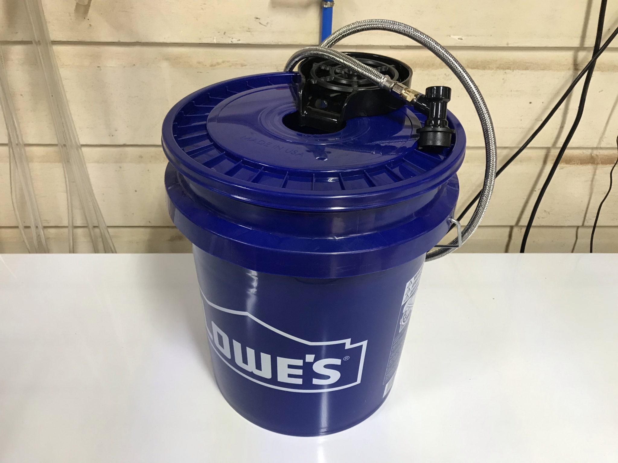
The fully assembled portable glass rinser
To use it, simply attach the liquid out disconnect to a Corny keg full of water, and use 10-15 psi of CO2 to push water to the glass rinser. The water doesn’t need to be kept as cold as beer for rinsing, so the whole setup can be easily toted around as needed without the need for a jockey box, ice, or even a table. May your patrons enjoy clean glasses at your next event!
Testing the portable glass rinser using the water keg in my keezer
After moving a few years ago and selling my fermentation chamber, I’ve been without proper temperature control for my beers. I’ve been fermenting them in the house—typically in the bathroom, which stays a bit warmer than the rest of the house. When the “shower beer” situation peaked at 25 gallons of beer, I realized I need to solve this problem sooner than later: I needed a way to ferment in the garage and control temperature. Time to build a DIY glycol chiller!
Too much shower beer!
Whereas I had previously built a fermentation chamber to control temperature via heating and cooling the air, this time, I decided to step up my game and move into glycol chilling. This would require fermentors capable of supporting a chilling coil, as well as the glycol chiller and circulation system. After some research, I settled on the Delta FermTank 14 gallon fermentor.
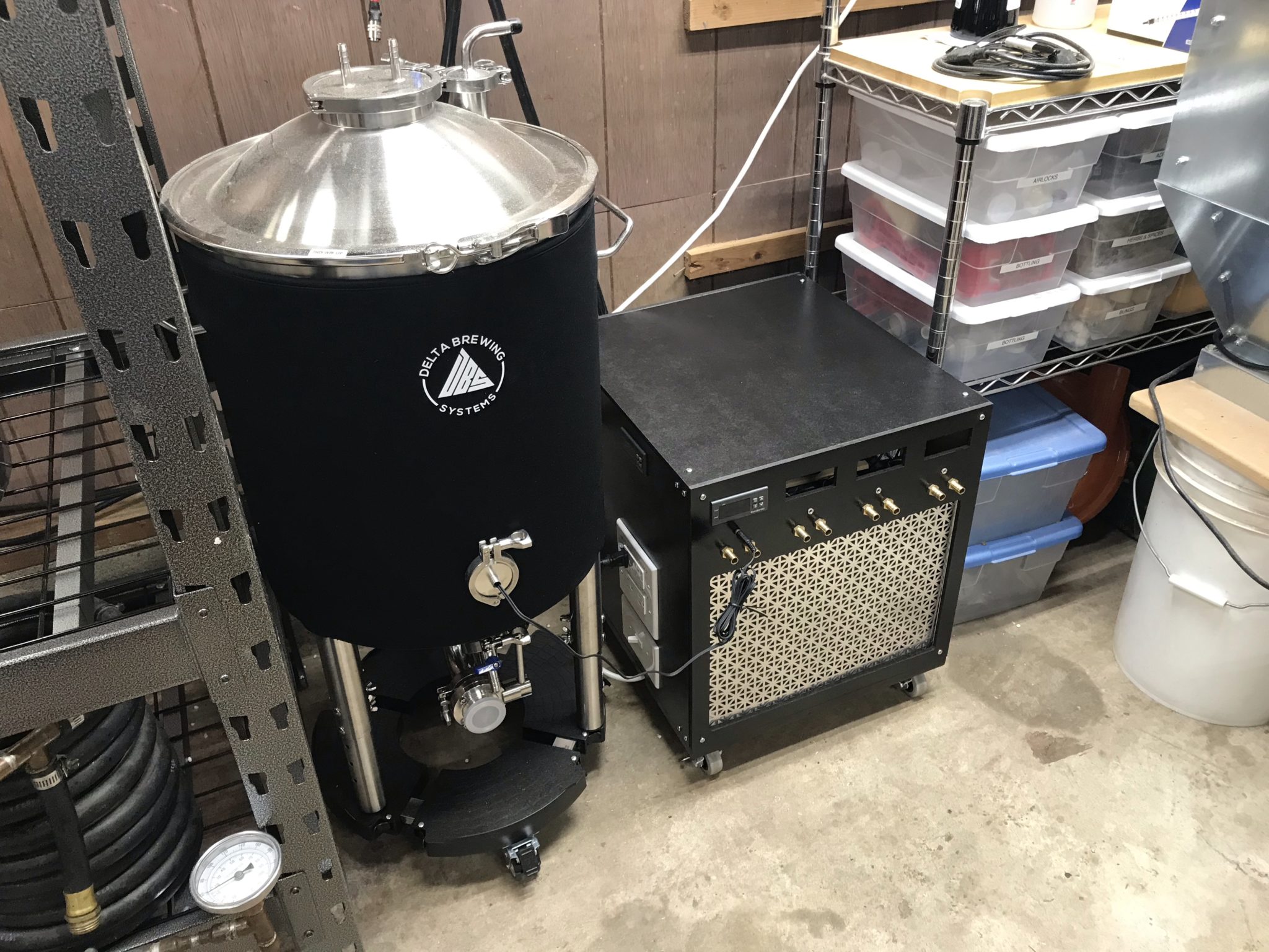
For the chiller, I stuck to my guns and went the DIY glycol chiller route using a window A/C unit and a cooler. But not wanting to be outdone, I over-engineered this thing to be more compact than the other DIY solutions I’d seen.
Parts
Midea 5000 BTU mechanical window air conditioner (Walmart)
The first step was to cannibalize the A/C unit. I set the temperature and mode to maximum cooling capacity, then removed the knobs and exterior case.
The A/C with front panel removedThe A/C with enclosure and evaporator fan removed
Then I went about slowly and carefully realigning the evaporator coil to fit into the cooler.
The scariest part of this whole build: reorienting the evaporator coil
Bypassing the thermostat
To make the A/C run whenever the temperature controller told it to, I had to bypass the built-in thermostat. I did this by folding up the probe inside the wiring enclosure, then wiring the two leads from the thermostat control to each other, bypassing the control completely. The thermostat could be removed completely, but since it wouldn’t save me any space in the overall build, I left it where it was.
The bypassed thermostat
Closing the gap
I used a hacksaw to remove the excess shaft coming from the fan motor to save space. I also made several modifications to the metal base plate of the A/C unit to facilitate placement of the cooler. If I were to do this again, I might just remove the base plate entirely and make my own mounts for the compressor, fan, and wiring enclosure.
The shortened fan motor shaftModifying the base plate with a hacksaw
To fit the cooler as close as possible, I also modified the wiring enclosure so the start capacitor could be reoriented 90º. This took a bit of cutting with tin snips and adding screw holes, but wasn’t too difficult.
The rotated A/C capacitor
I shopped around for the smallest cooler I could find that would fit the coil. This would minimize both the amount of glycol needed and the chilling time. With the modifications to the A/C base plate, wiring enclosure, and fan motor shaft, I was able to snug the cooler up very closely in the A/C footprint.
A test fit of the cooler with preliminary wiring mockup
Wiring the chiller
The wiring for this DIY glycol chiller was a bit of an evolution. I wanted to keep it as flexible as possible while using easy-to-get components. I initially started out with house wiring components, but ended up using a combination of house wiring and stranded project wiring. To handle the majority of the wiring within the enclosure, I bought a spool of 14-gauge stranded wire and several terminal blocks.
The end result is a chiller with a light switch as the main power switch, standard outlets for powering external heaters for each fermentor, and internal terminal block wiring for running the A/C unit, glycol circulation pump, exhaust fan, and each fermentor’s pump, as well as all the temperature controllers.
For components like the circulation pump that had standard power cords, I trimmed the plug off and crimped on spade terminals to connect them directly to the terminal blocks. For components like each fermentor’s glycol pump that have a wall wart, I modified cheap extension cords in a similar manner, so the power adapter plugs into the extension cord, and the extension cord is wired directly to the terminal block.
The terminal block wiring and modified power cords
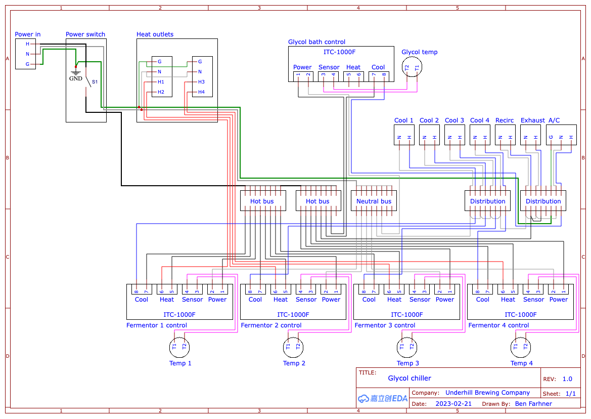
This is the final wiring diagram I arrived at after a few iterations and simplifying things as much as possible:
The final wiring diagram
Building the Enclosure
I originally started building the enclosure from 3/4″ plywood that I had on hand, but quickly realized I needed something thinner to be able to panel-mount the components. I also wanted something that could be more easily removed for service. In the end, I used fiberboard panels mounted to aluminum angle brackets on a plywood base.
Original plywood enclosureNew and improved fiberboard enclosure on casters
I designed the chiller to be able to support a total of 4 fermentors. I only have 1 right now, so I haven’t verified that it’ll work at that capacity, but as I expand I’ll be able to test it out. If it can’t handle 4 a time, I could modify the build and enclosure as necessary.
Since the temperature controllers support both heating and cooling, I designed this system with outlets for heaters. Each outlet is controlled separately, so each fermentor’s heating jacket can be plugged in constantly and only receive power when it needs to raise the temperature.
The side of the chiller, featuring the power switch, heating outlets, and glycol bath temperature control
With the initial assembly of the enclosure, I realized there wasn’t enough airflow inside when the A/C was running. In fact, this led to the A/C fan motor overheating and melting its plastic mount! Fortunately, I was able to salvage it without any major impact to function. To solve the airflow issue, I added an exhaust fan that runs constantly, even with the A/C off. I also added a vent hole in the bottom of the enclosure to allow fresh air in.
The exhaust fan for ventilation inside the glycol chiller
Now that I no longer have my fermentation chamber, I needed a new temperature controller to control a fridge for fermentation or serving.
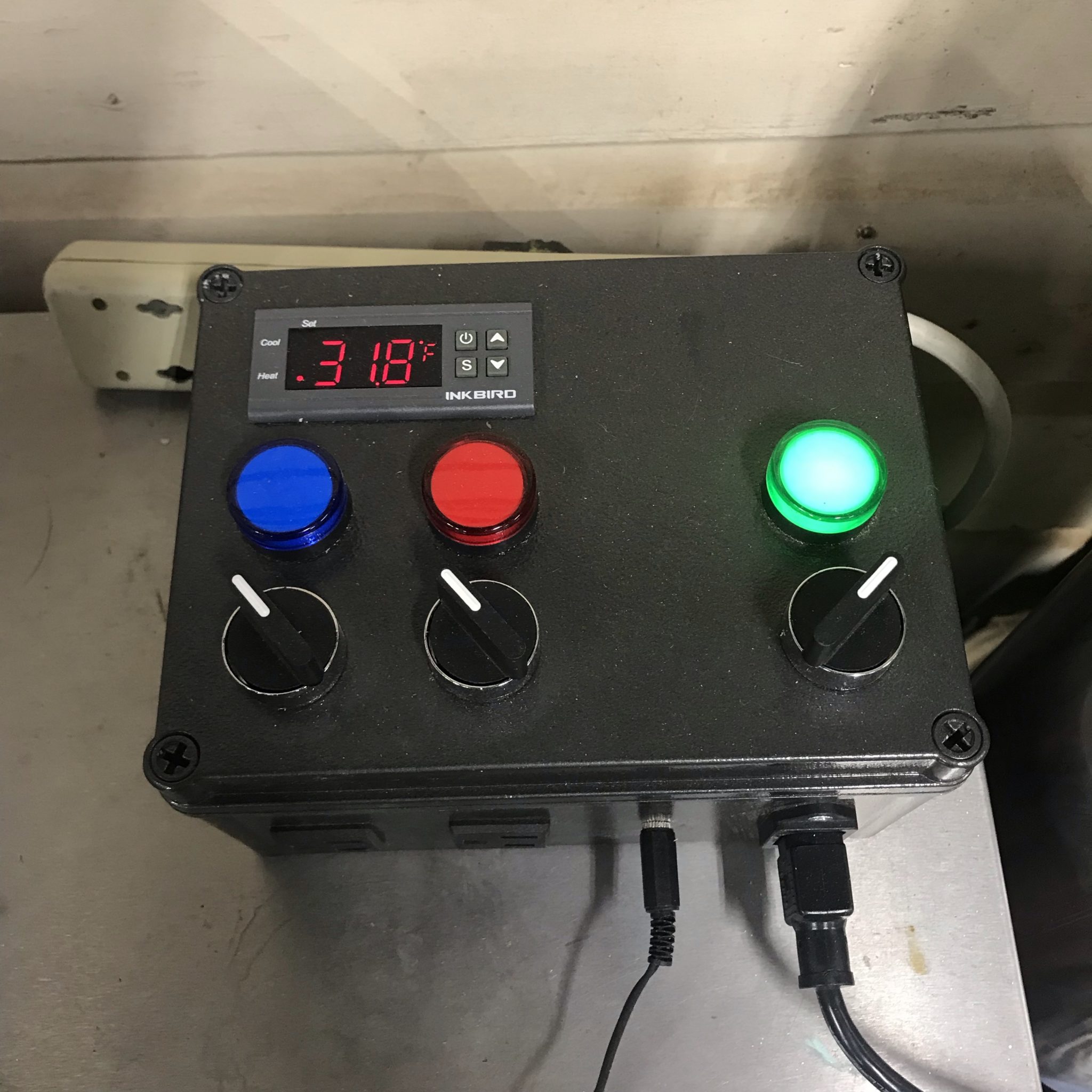
I wanted something that would match my brewery control panel, so I went a little above and beyond on this build, but I’m really happy with the results.
Completed temperature controller, monitoring fridge temperature
(1) Panel mount 1/8″ (3.5 mm) TS or TRS jack (Amazon)
14 ga wire
Build
First, I prepped the project box by drilling holes for the 22 mm indicators and switches using a 7/8″ Forstner bit. The hole for the 1/8″ jack was drilled with a 1/4″ Forstner bit.
For the square holes, I found the easiest way was the drill a hole in the corner, saw from the holes to the other corners with a hacksaw, then score the sides and bend them in the break them out. I cleaned up the edges with a utility knife.
Once all the mounting holes were cut, I did a test fit to make sure it all fit correctly.
Then I removed everything, scuffed up the project box with some 150 grit sandpaper, and spray painted it with the same Rustoleum black hammered finish paint that I used for the brewery control panel.
Wiring
I used 14 ga house wiring for everything inside the box except the sensor wires, for which I used smaller 18 ga wires that I had left over from a ceiling fan.
I used wire nuts for all the junctions but it would look a lot cleaner with terminal blocks instead, so I’ll probably do that for version 2.0.
Wiring diagram
I put together this wiring diagram to make assembly easier. It’s pretty straightforward if you’ve ever wired up an ITC-1000 or STC-1000 controller before.
Final Product
I put some industrial strength Velcro on the back to secure it to my beer fridge and ran the temperature probe to a jar of water inside the fridge. For now, it just monitors the temperature of the fridge as the fridge itself maintains serving temperature pretty well, but ultimately, I’ll be using this to control a fridge or freezer for fermentation.
I’m serving Underhill beers at my first-ever homebrewing event! If you’re in the Northwest Arkansas area on October 8th, 2022, come check out Brewtober Chilifest at St. Raphael Catholic Church in Springdale, AR. I’m very excited to share these brews with a wider audience and get feedback on them, so I hope you can make it! I’ll be serving the following beers:
Table
A Belgian-style single ale with coriander and orange peel ∴ 3.8% ABV
Lily the Pink
A wheat ale with raspberry and hibiscus ∴ 4.2% ABV
The Nars
A piña colada milkshake IPA with BRU-1 and Sabro hops and lactose ∴ 6.5% ABV
Old Concoction 2022
An imperial gruit stout with honey, mugwort, chamomile, licorice root, yarrow, orange peel, and vanilla bean. No hops! ∴ 8.9% ABV
For Christmas 2021, I was gifted an inclinometer to install in my 4Runner. It was an inexpensive model from Amazon, and in true fashion, I couldn’t help but disassemble it and make it my own. I made a few changes, starting with how it mounts.
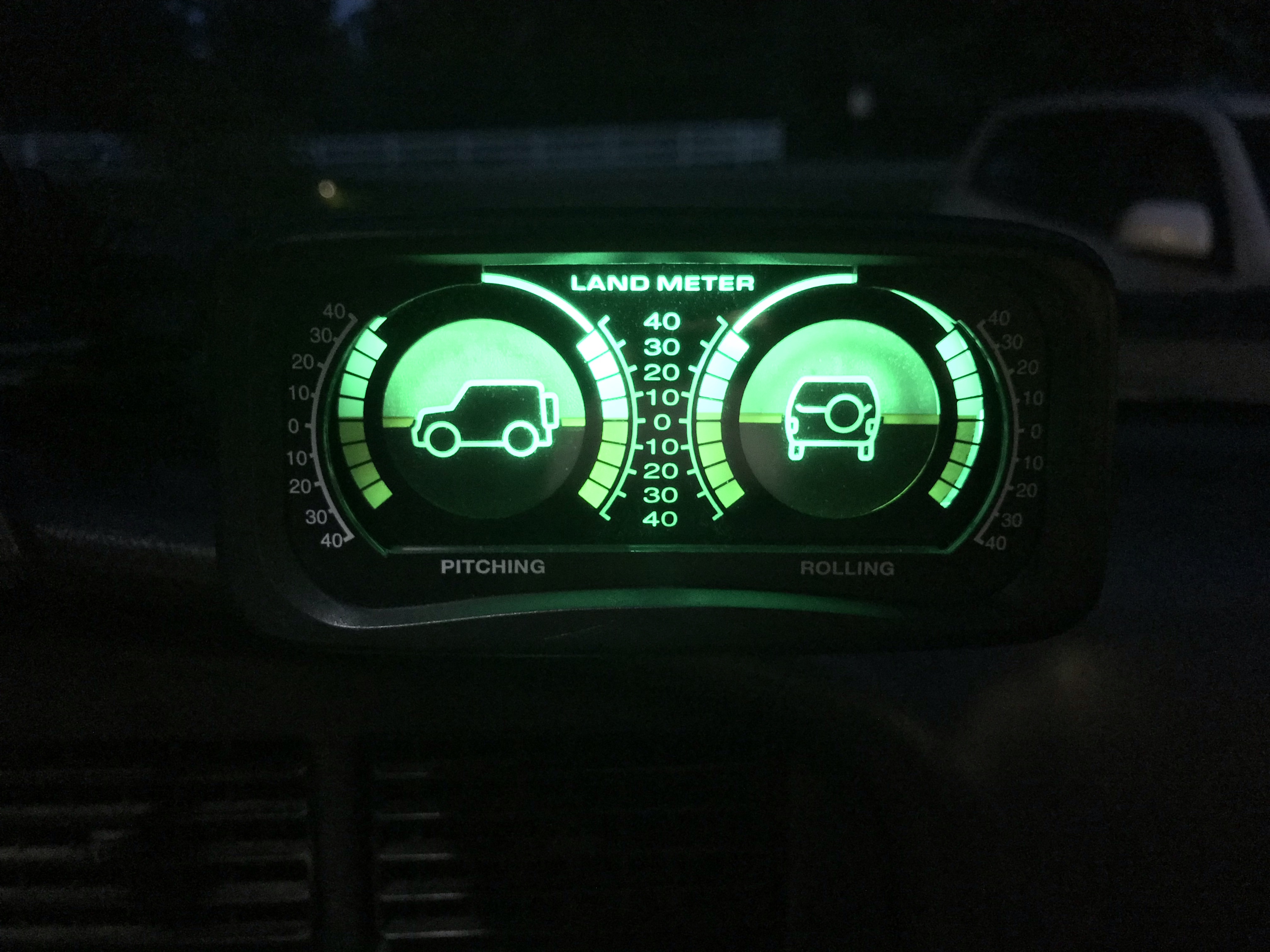
The inclinometer, modded and mountedThe inclinometer at night, matching the rest of the green LED dash lights
Custom Mount
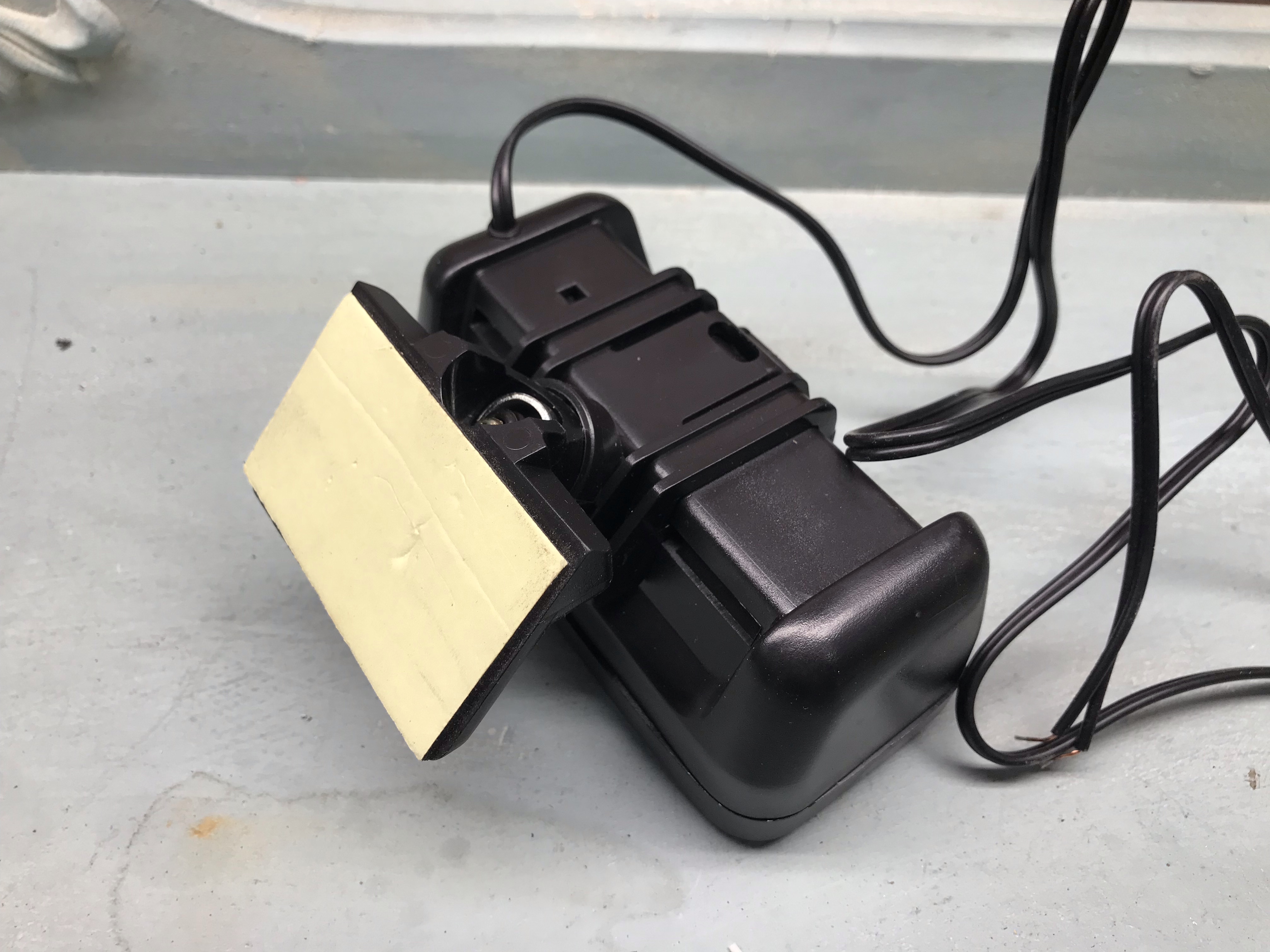
The inclinometer came with a flat mounting plate with an adhesive backing, but the dashboard in my ’92 4Runner doesn’t have a nice flat spot that would work where I could see it from the driver seat. Since I was in the process of installing some RAM Mount tracks, I decided to convert the inclinometer to work with the RAM Mount system instead.
The original flat mounting plate
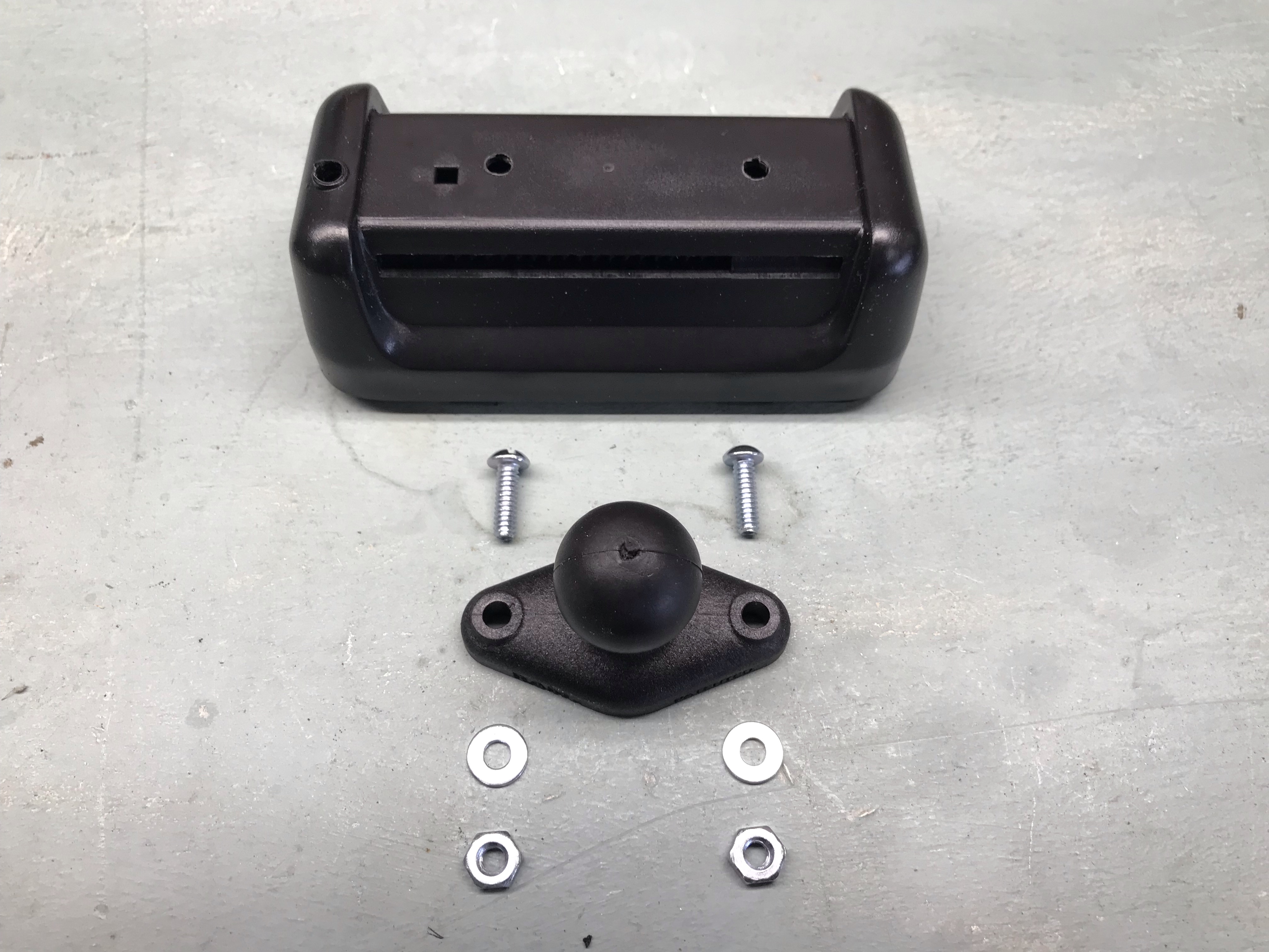
Thankfully, the original mounting plate just snaps off the back, leaving a nice flat surface to work with. Using the RAM base as a template, I marked and drilled 2 holes for the screws.
Holes drilled and parts laid out
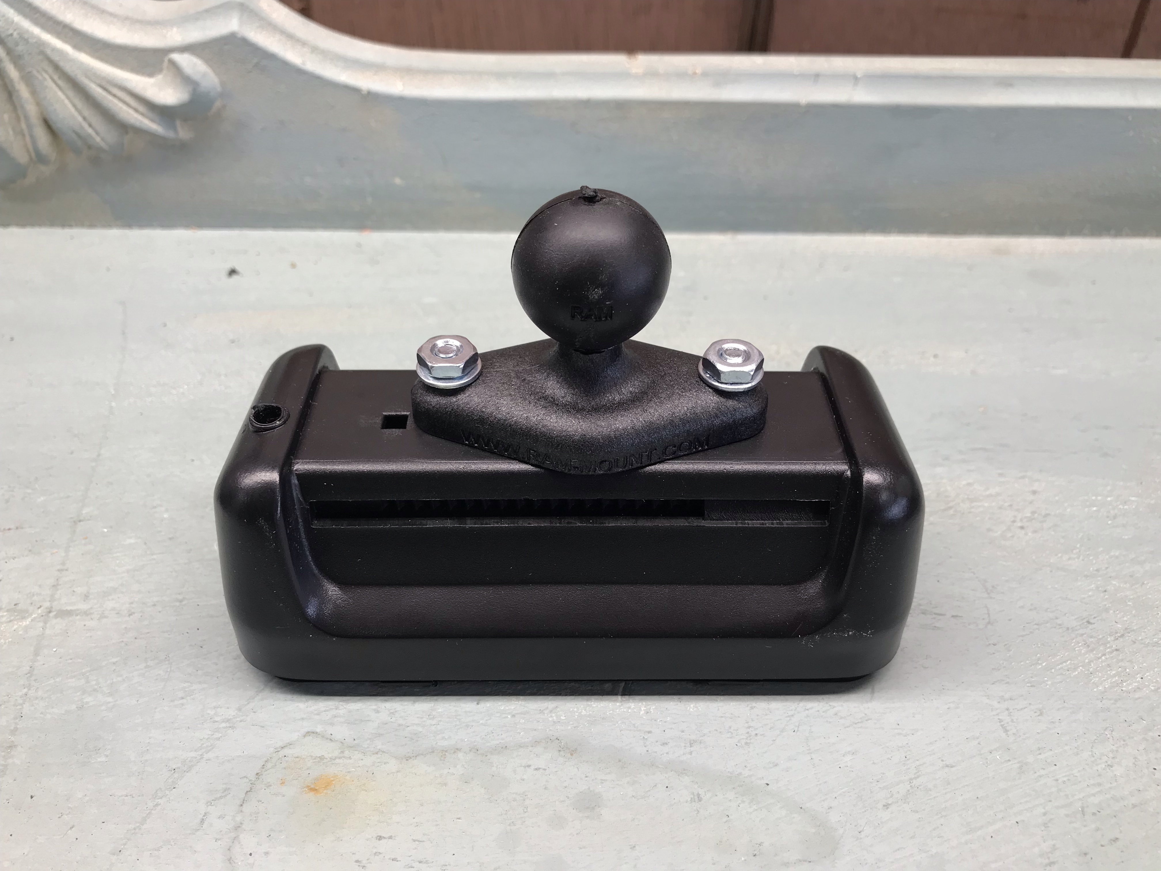
Note that I mounted it slightly off-center to leave room for the square hole, which is a notch for the wires to hook on inside. The offset also worked out well for positioning it in the vehicle, moving it slightly further away from my phone mount.
The new RAM base installed
A couple of additional pieces are necessary to mount this on a RAM track: a T-track ball mount and a double socket arm
LED Lighting
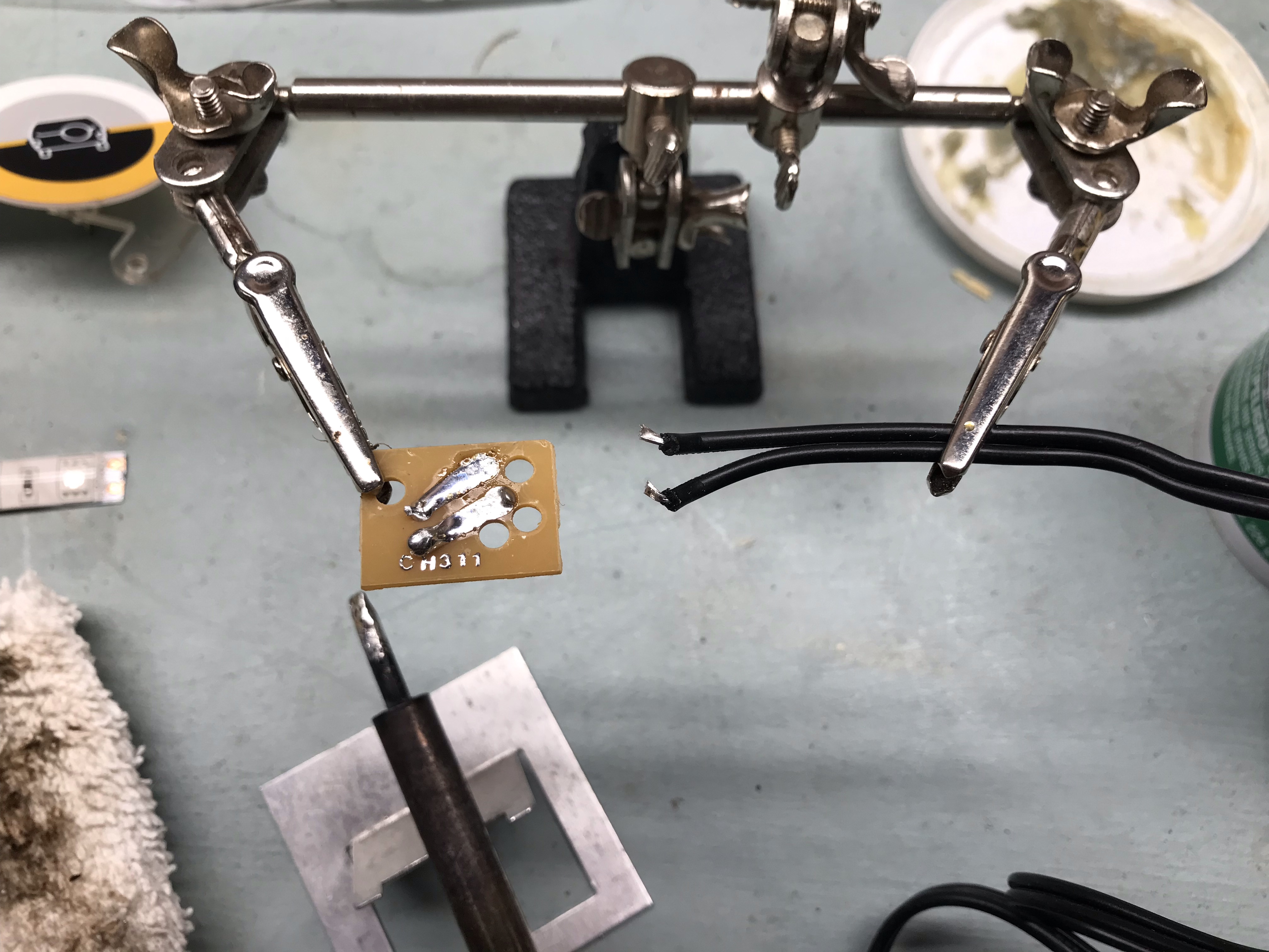
The single factory incandescent bulb wasn’t cutting it for me since it didn’t match the other green LED dash lights I had put in place. Fortunately, it was pretty easy to replace the bulb with a strip of green LEDs with a soldering iron. The bulb was mounted to a board with the power supply wires soldered to it. I could reuse the board for the LED strip, so I desoldered the wires and bulb.
Desoldering the wires and incandescent bulb from the board
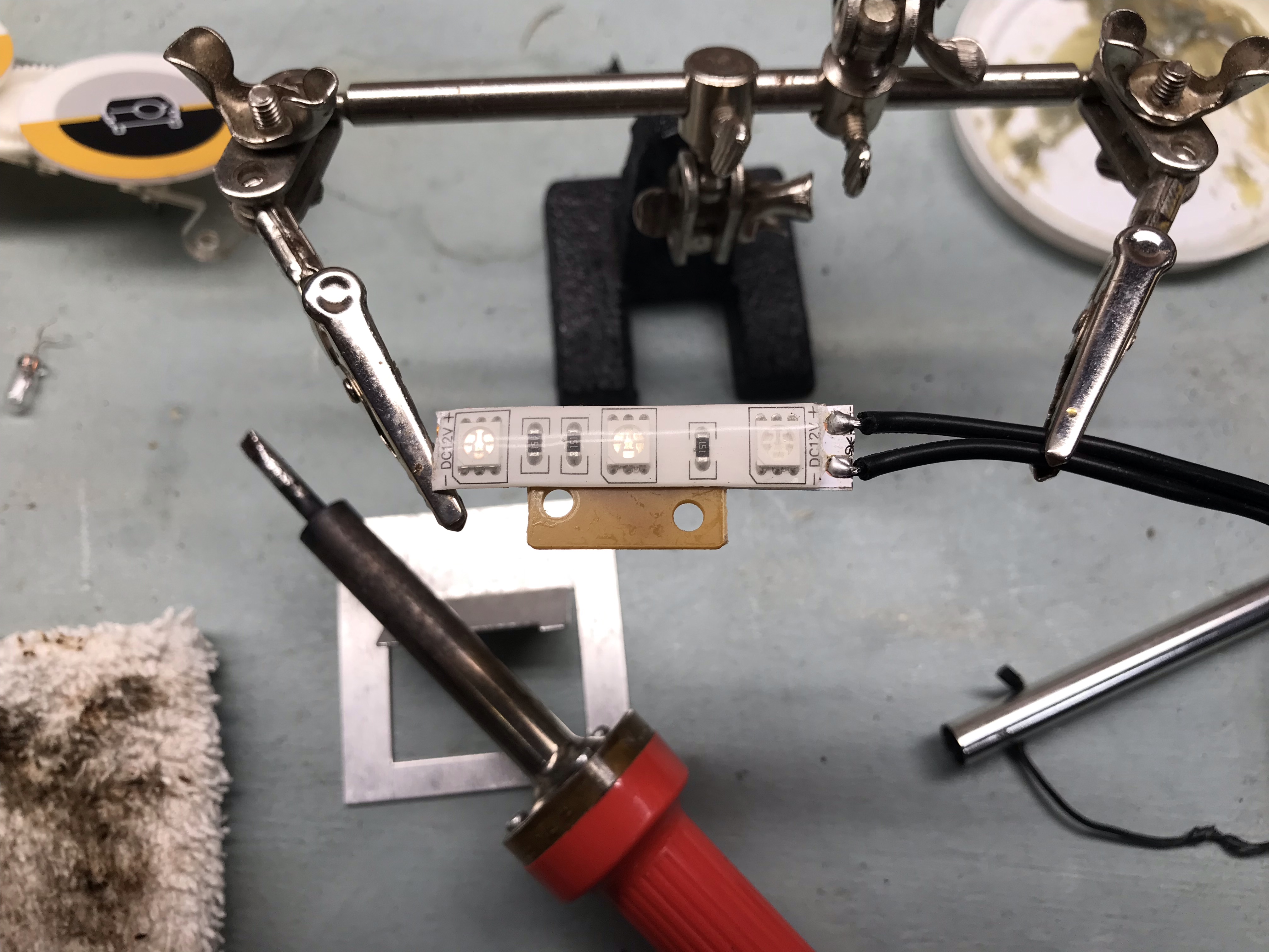
Then I soldered the wires to the LED strip, peeled off the protective backing, and stuck it to the board.
The LED strip attached to the board with wires soldered to it.
Then it was just a matter of reinstalling the board in the inclinometer like it was before.
The board reinstalled with the LED strip
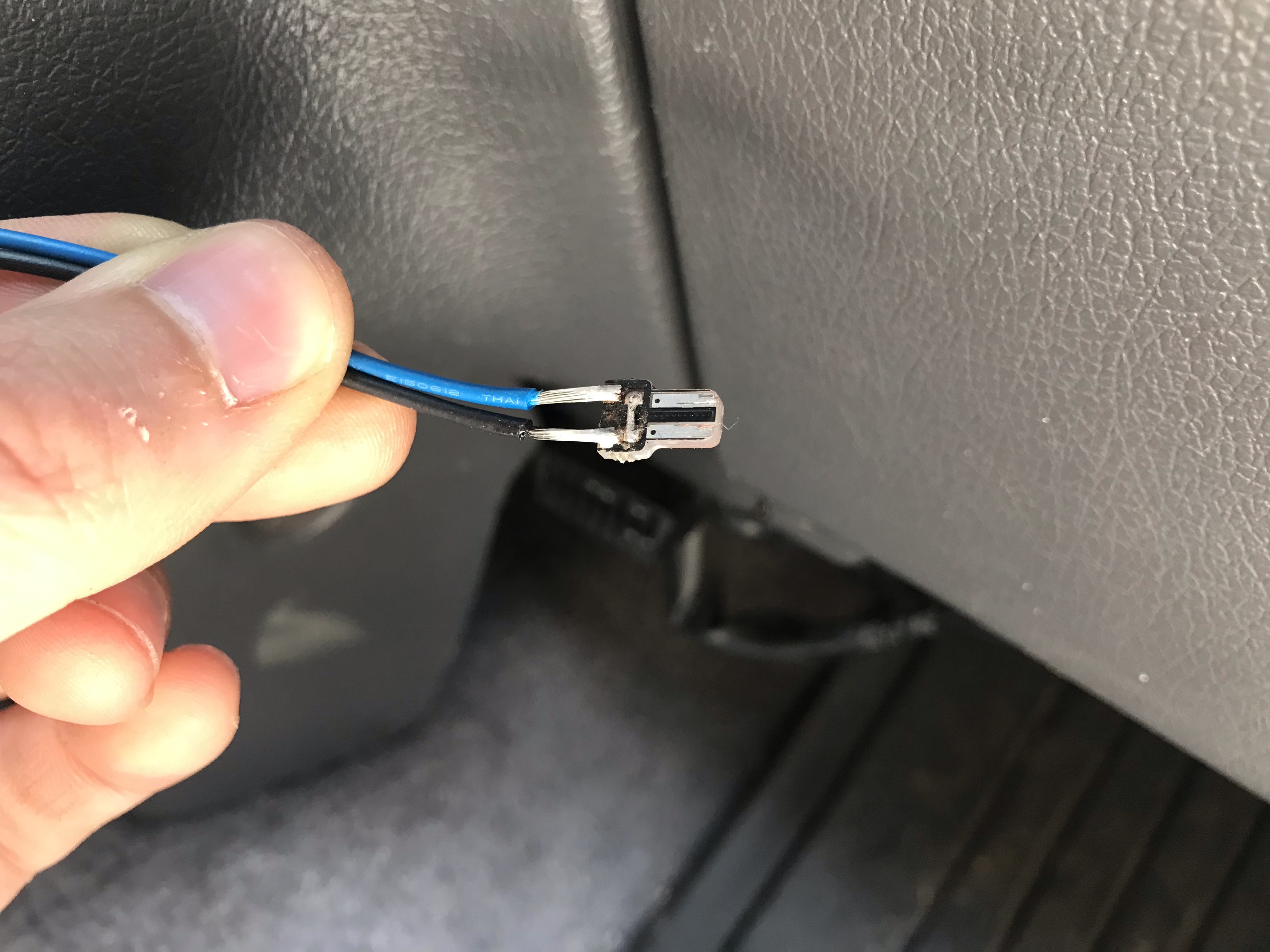
To get power to the inclinometer, I drilled an extra hole in the dash inside the RAM mount track where I could feed the wire. Then, I actually disassembled a T5 LED bulb (size 74 factory bulb) and soldered a couple of lead wires on it so that I could easily plug it into a factory dash bulb location. Since my Midland MXT115 GMRS radio is now where the ashtray used to live, the ash tray bulb socket wasn’t being used, making it the perfect candidate to tie into and keep tucked behind the radio.
Modified T5 LED bulb with lead wiresThe inclinometer illuminated with the green LED strip
Cost
The inclinometer was free to me, but RAM Mount parts aren’t terribly cheap. However, they’re such a great product, this was one of those “buy once, cry once” situations in my book. That said, see if you can buy them on eBay with free shipping since RAM Mount charges a lot for shipping!
Last weekend, we attended Rendezvous in the Ozarks for the second year in a row. It was rainy the first couple of days, so we brought along a 10’ x 10’ canopy to give us cover between our ground tent and the back of the 4Runner. But man! that thing is heavy and bulky.
So when we got back from camping, I started looking into alternatives. There are lighter-weight canopies out there, and also a really cool product called the MoonShade, which is basically a fancy lightweight vehicle awning. But I’m overlanding on a budget, and $325 is a bit steep for an awning. Enter the DIY Poor Man’s MoonShade.
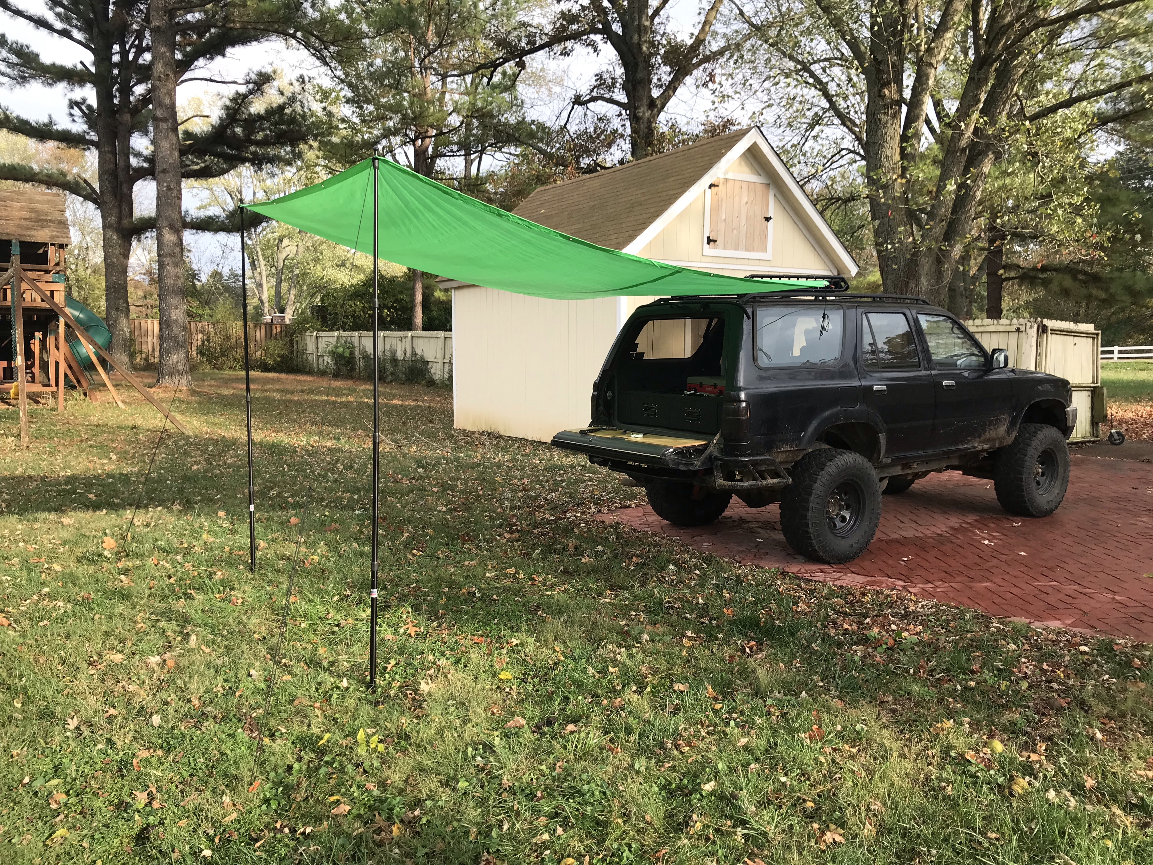
The basic concept consists of a tarp with one side affixed to the vehicle and the opposite side supported by 2 poles. Since I want this to come off the back of the 4Runner, and it’s pretty narrow, I also need a strut to hold the tarp out wider than the 4Runner, similar to the MoonShade’s solution. I also want to run guy lines from the corners to help keep it taut.
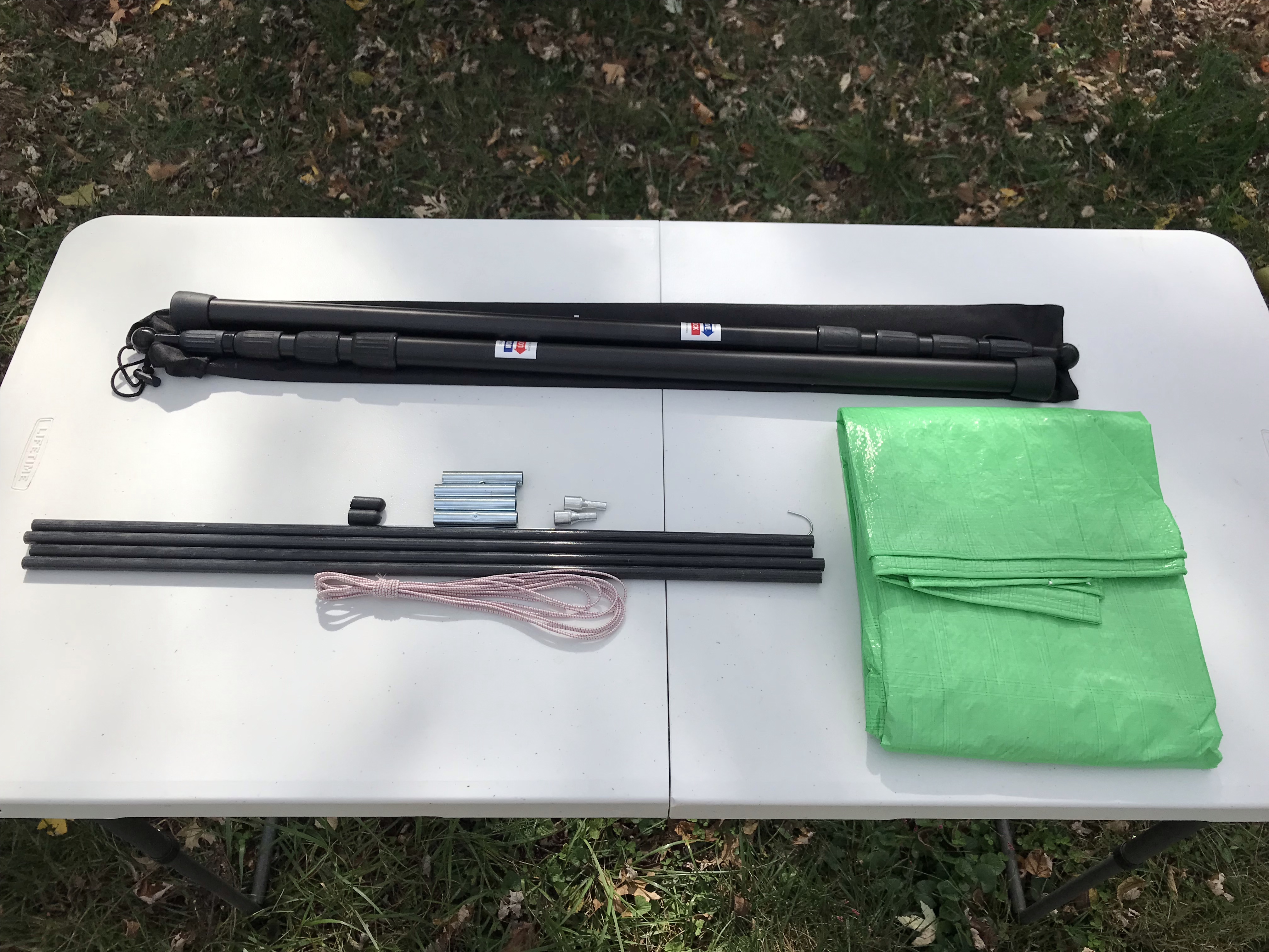
Fiberglass tent pole repair kit with crimped ferrules. That last part is important because it allows the pole to insert into the tarp grommets.
2-4 Tent stakes
2 Carabiners (optional)
X ft of paracord
The nice thing about fully adjustable tent poles is that you can set up one slightly taller than the other, or both shorter than the vehicle, to create a slope to shed rain.
The tent pole repair kit was the key piece to this puzzle for me. I was having trouble finding a double-ended tent pole with 2 pins for the grommets like the MoonShade has, and was seriously considering fabricating something myself until I stumbled across this kit with enough poles and pieces to make exactly what I needed.
Build
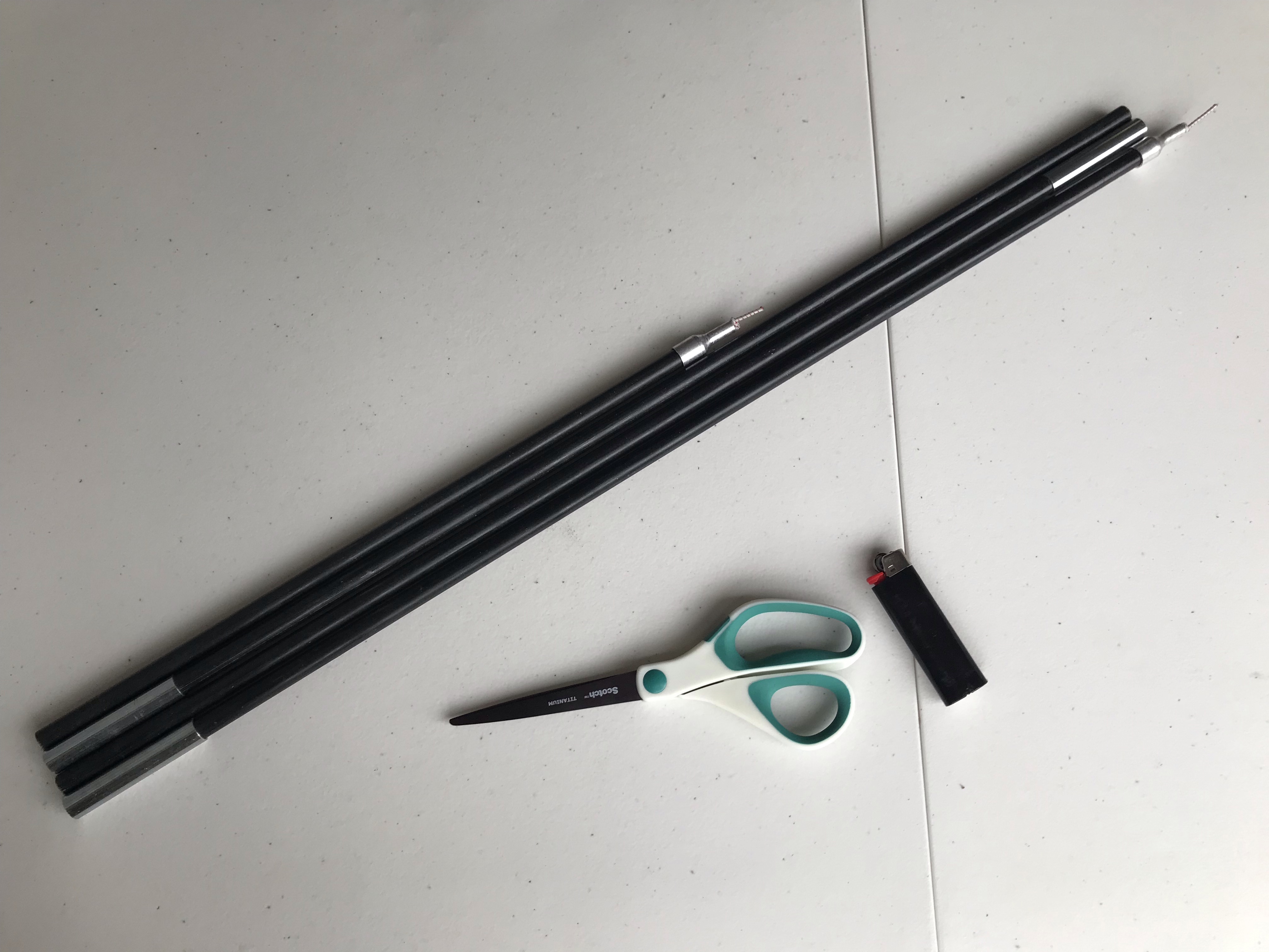
The main thing that needed to be built was the strut. I assembled the tent pole pieces and laid them out on the 8’ side of the tarp, with the pin end in one of the grommets, and set the other pin end in the opposite grommet to see where to cut the last tent pole section, marking it with a pencil.
Measuring to cut the fiberglass tent pole
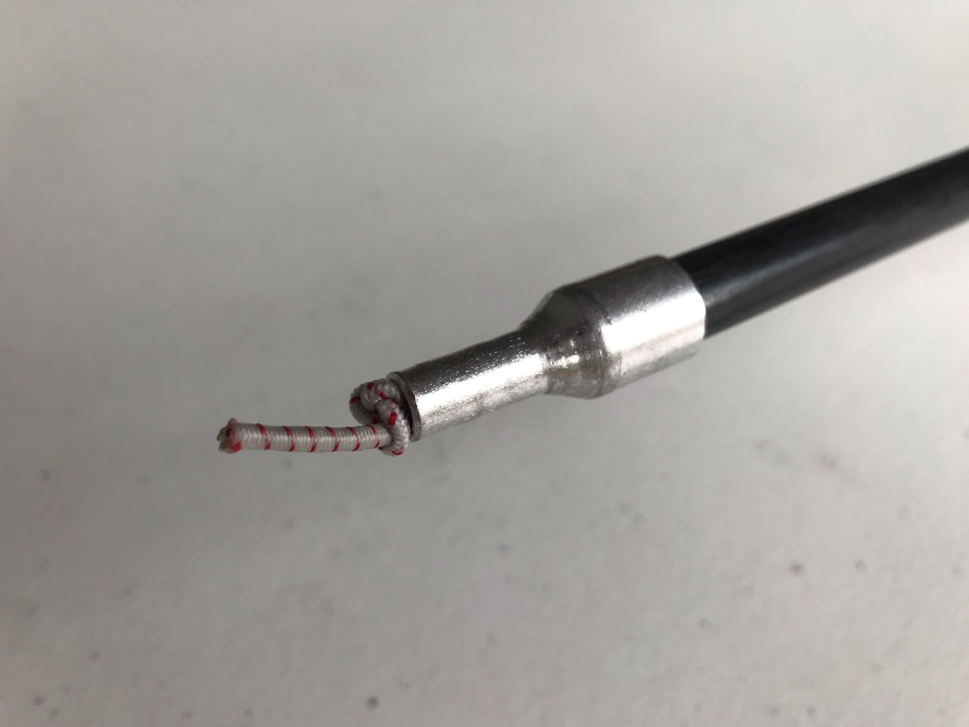
Then I cut the tent pole section with a hacksaw, sanded the cut end, and fully assembled the tent pole with the provided shock cord. I tied the shock cord after the pin ends so the whole assembly is contained, and melted the ends of the shock cord to keep it from fraying.
Shock cord tied after the pin endThe completed strut
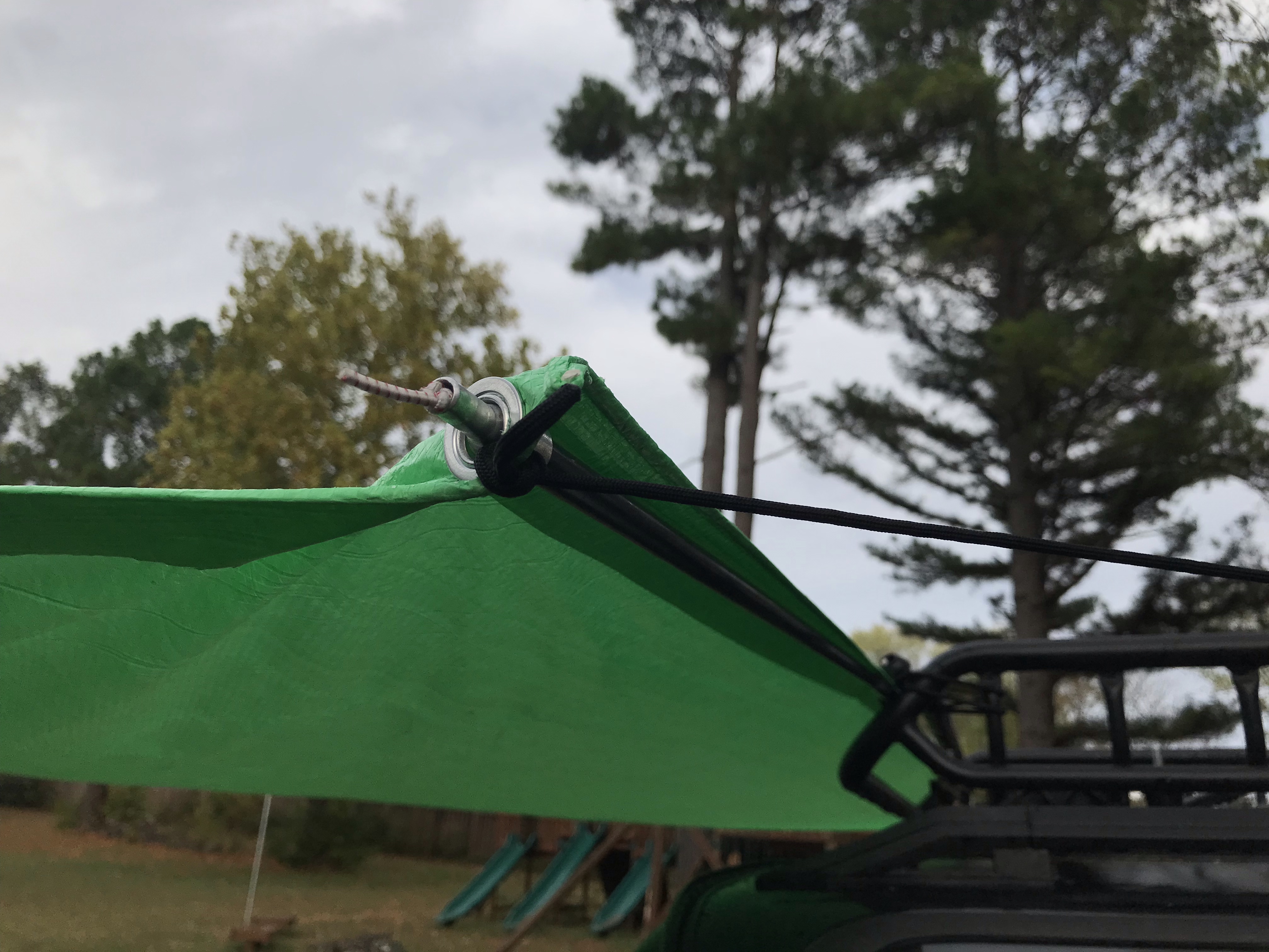
I also needed a way to affix the strut to my vehicle. MoonShade offers a variety of attachment methods, but since I have a roof rack, I kept it simple and used a couple of tarp ball bungees to hold the strut to the roof rack. In my case, the tarp grommets lined up pretty close to the sides of my roof rack, so I loop the ball bungees through those as well to hold everything together.
Ball bungee in the background holding the strut and tarp to the roof rack
The last piece is the guy lines. I measured out paracord with enough length to tie taut-line hitches for adjustability and tied them permanently to all 4 corners of the tarp. On the vehicle side, I actually attached these to my roof rack with carabiners, but they’re long enough I could stake them to the ground instead.
Guy lines attached to the roof rack
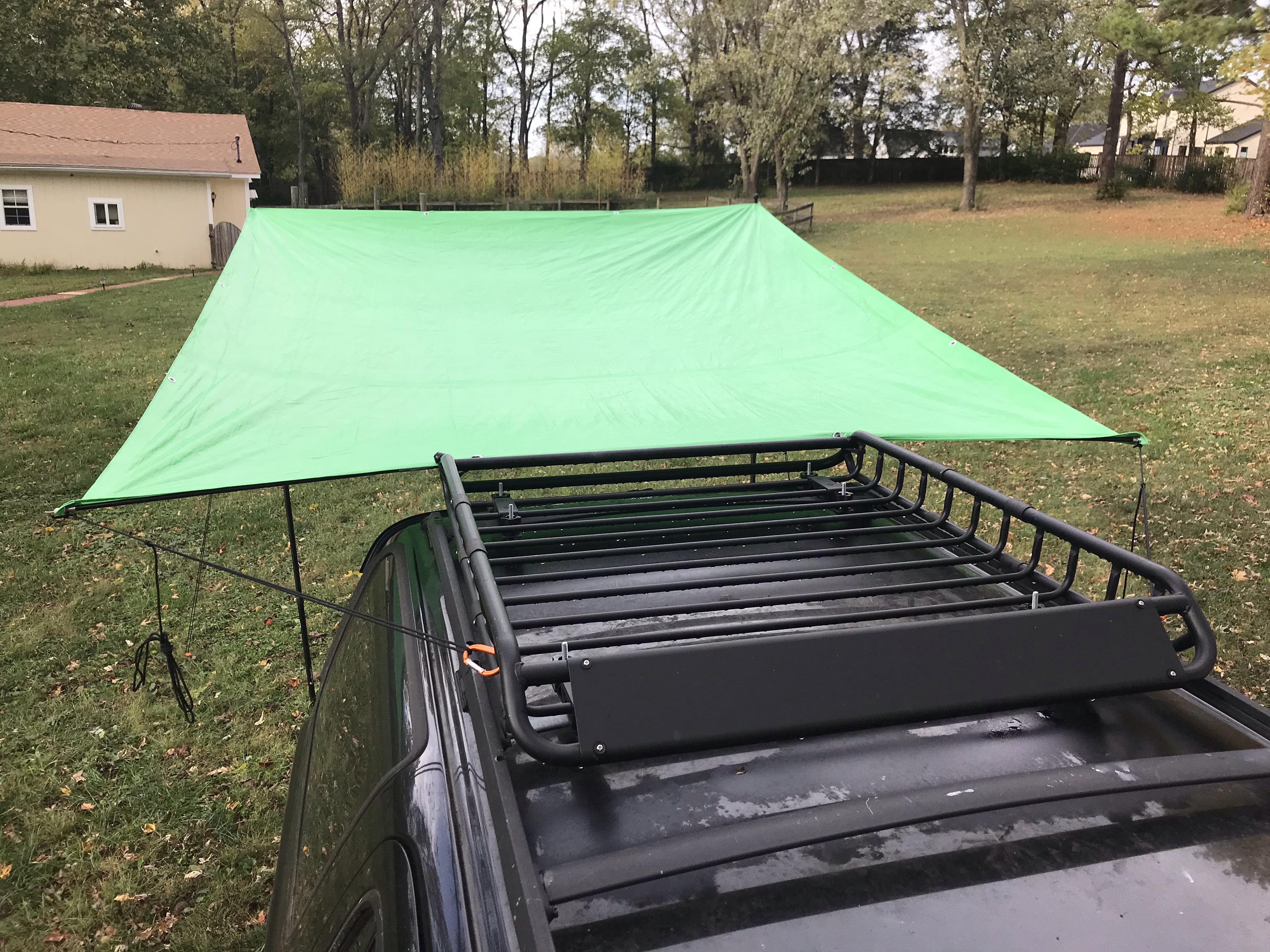
The far side is supported by the telescoping tarp poles and held taut with guy lines staked to the ground.
The Poor Man’s MoonShade
I need to play around with tensioning to make sure water doesn’t pool in the center, but overall, I’m really happy with this build. It’s easier to set up with 2 people, but I can tear it down by myself in just a couple of minutes, which is a lot faster than my 10’ x 10’ pop-up canopy!
When I swapped a 3.4 engine and ECU into my 4Runner, the donor vehicle had an automatic transmission, and the ECU expected to see signals from the automatic transmission solenoids. Without those signals, it would illuminate the check engine light, masking any real issues I may need to investigate. To avoid that, the signals can be spoofed or simulated using resistors. All that’s needed is a little wiring and soldering.
Supplies
(3) 15 ohm power resistor, rated for 25W or higher
(1) 5 ohm power resistor, rated for 50W or higher
18-20 AWG wire
Project box or mounting surface
Tools
Wire cutters/strippers
Soldering iron and solder
Pinout
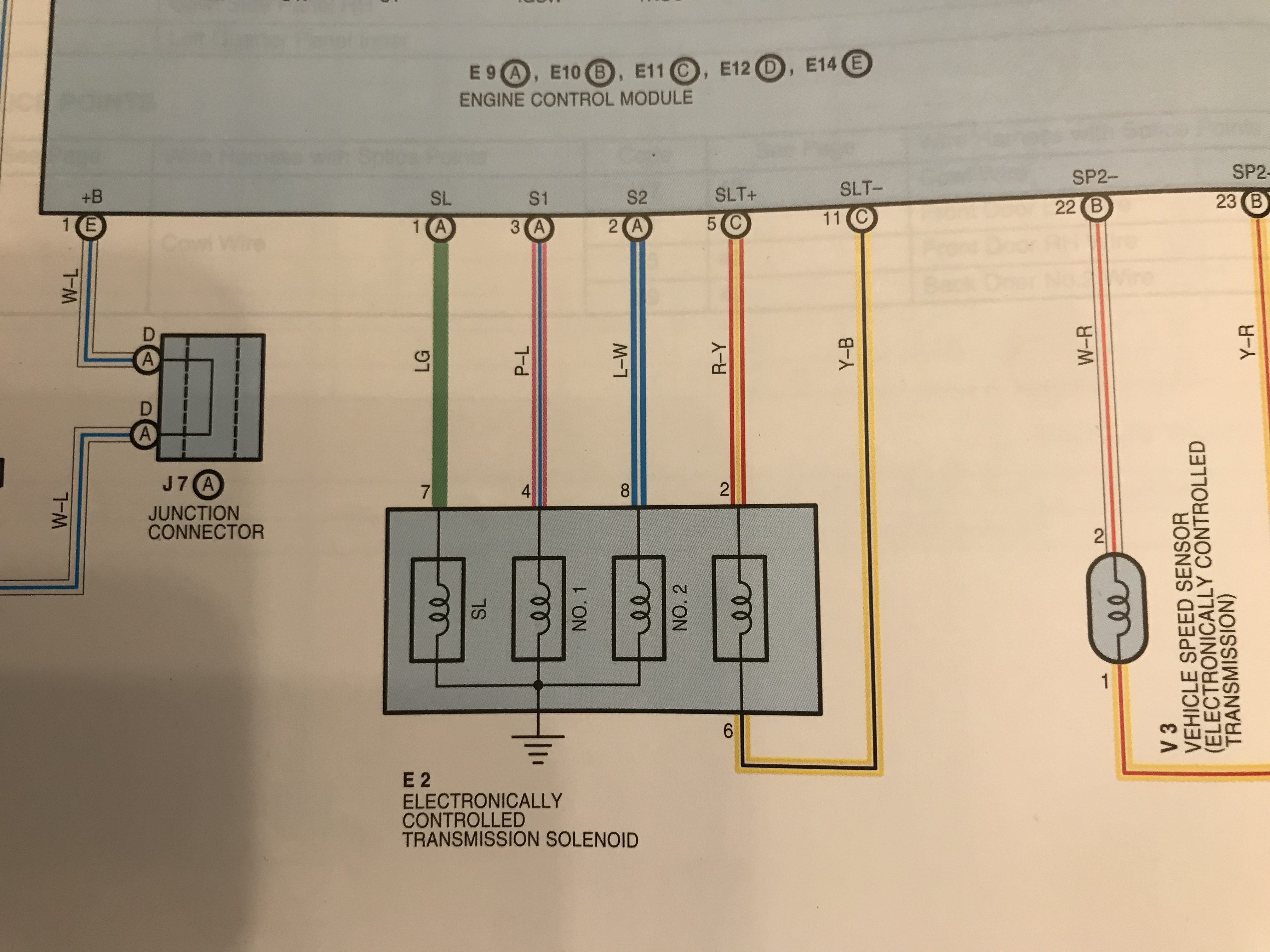
A 3rd gen 4runner auto ECU will have 5 pins for the Electronically Controlled Transmission (ECT) Solenoid. In a 2002 4runner, these pins are as follows:
SL (Connector E9 Pin 1, LG)
S1 (Connector E9 Pin 3, P-L)
S2 (Connector E9 Pin 2, L-W)
SLT+ (Connector E11 Pin 5, R-Y)
SLT- (Connector E11 Pin 11, Y-B)
Diagram for 2002 4Runner with automatic transmission
The SL, S1, and S2 wires all go through the solenoids to ground. The SLT+ wire goes through the solenoid and back to the ECU to the SLT- pin.
You will need to look at the Electronic Wiring Diagram (EWD) for your 3.4 engine’s model year and confirm the ECU pin locations and wire colors because they vary by year.
Theory
Each solenoid has a range of resistance and voltage that the computer expects to see.
The SL, No. 1, and No. 2 solenoids all have a resistance of 11–15 ohms, and range in voltage from < 1.5 V to 9–14 V, depending on which gear the auto transmission is currently in. Using the formula I = V / R, we can therefore calculate the maximum wattage as 14 V / 11 ohms = 17.8 W. To be safe, I rounded this up to be able to dissipate at least 25 W of power.
The SLT solenoid has a resistance of 5.0–5.6 ohms, and pulses between < 1.5 V and 10–12 V when the engine is idling. Consequently, we can calculate the maximum wattage as 12 V / 5 ohms = 28.8 W. I rounded this up to safely dissipate at least 50 W of power.
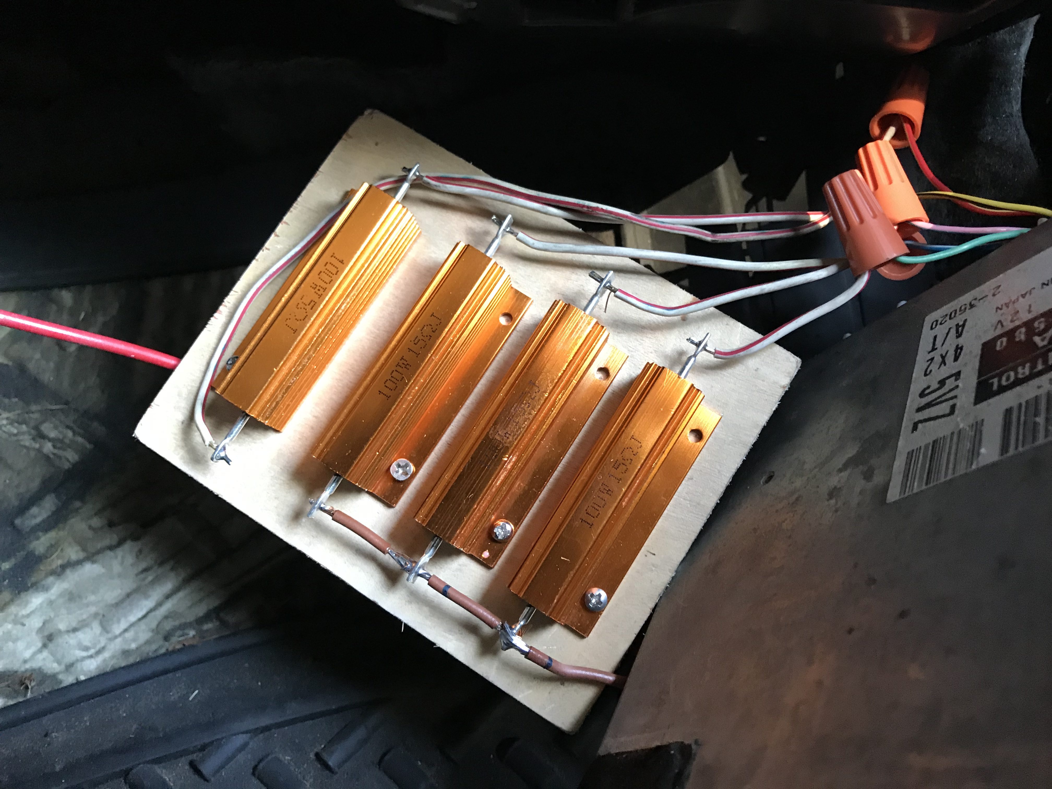
Based on this information, we can use 3 power resistors rated for 15 ohms and 25 W to spoof the SL, No. 1, and No. 2 solenoids, and we can use 1 power resistor rated for 5 ohms and 50 W to spoof the SLT solenoid.
Build
Essentially all that needs to be done is soldering wires to the resistors and then connecting the wires to the ECU and ground accordingly.
The wires to the ECU connectors should ideally be joined with a lineman splice to the connector wires and then soldered. This will create a very strong connection to avoid signal interruption to the ECU. Optionally, instead of a direct splice, the wires can be crimped and soldered to terminals or a multi-pin connector so that the simulator can be easily removed from the ECU.
Prototype of the simulator. Notice how the brown ground wires are chained together at the bottom. The wire nuts are very temporary and shouldn’t be used long-term!
There are 2 options for the ground wire coming from 3 of the resistors:
Run it directly to a bolt on the chassis for a direct ground
Splice it into the ground wire coming from the ECU
I opted for option 2 to keep everything ECU-related contained and not have another ground point to worry about.
Testing
Once everything is wired up and the simulator is connected to the ECU and properly grounded, then the ECU should no longer through a Diagnostic Trouble Code (DTC) related to the automatic transmission solenoids. You may need an OBD-II port connected to your ECU to verify this, but if this was the only issue causing the check engine light to illuminate, then the check engine light should no longer be on!
Cost
This was a pretty cheap fix. I only needed to buy the power resistors, and was able to use wires and hardware I already had on hand.
15 ohm power resistors: $15.60
5 ohm power resistor: $7.70
Scrap wires: free
Wood mounting plate: free
Wire nuts: free
Total cost: $23.30
I’m planning to revisit this mod in the near future to tidy it up and move it to the engine bay. The resistors still get pretty toasty, so I’ve slipped the whole assembly into an old coffee can that sits on the passenger floorboard for now so my wife doesn’t burn her foot!
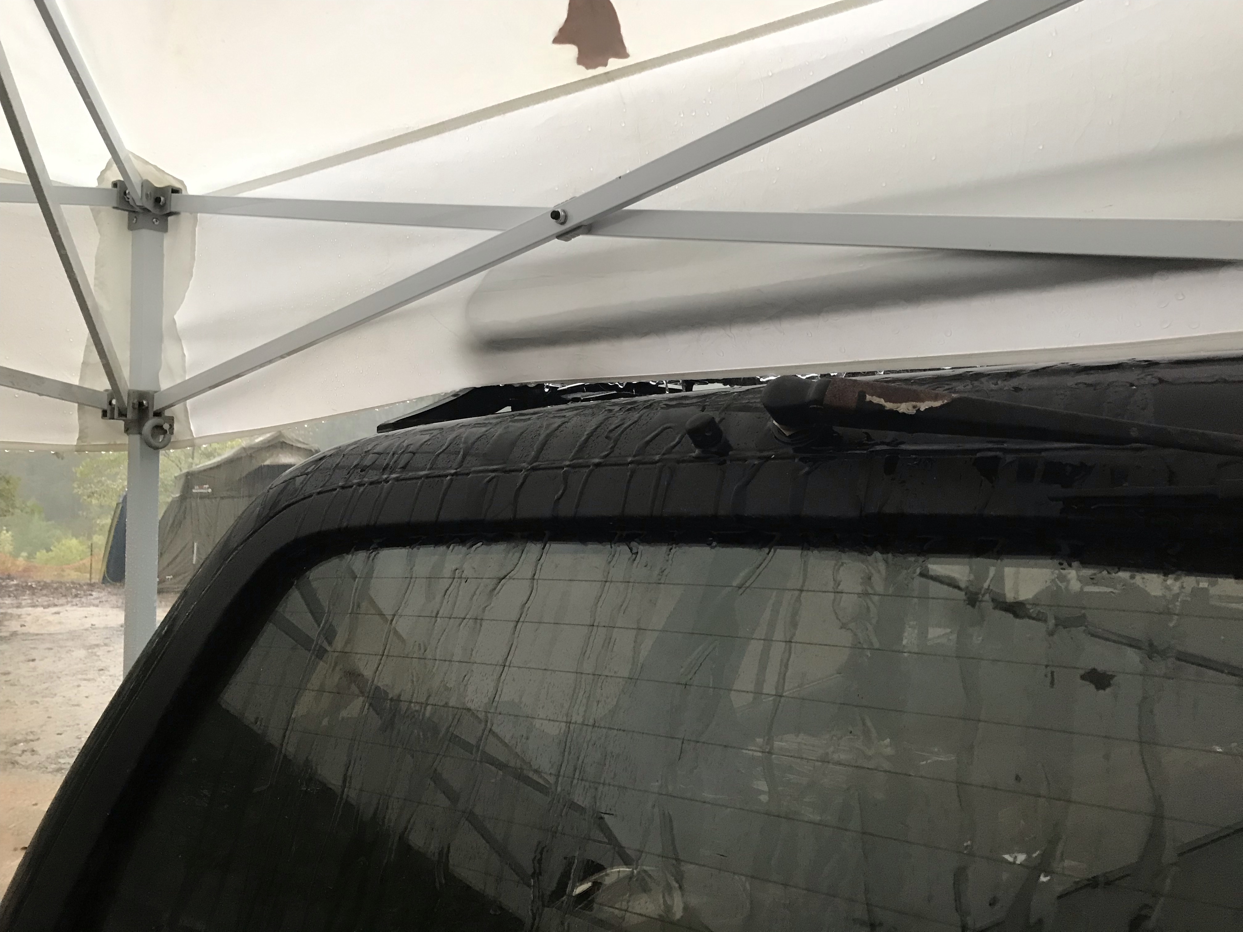
One of the (few) flaws of the 2nd gen 4runner, in my opinion, is the lack of a drip rail above the rear window. Even if the rear of the vehicle is under cover (such as my Poor Man’s MoonShade), if the rear window is open, rain on the roof will run straight into the cargo area!
I should be able to open the rear window under cover without getting rain in the back!
I spent several hours trying to find someone else who had solved this problem before, and maybe my Google-fu is getting rusty, but I was surprised that I couldn’t find anyone else doing something about this!
I think the ideal long-term solution would be to weld a proper drip rail above the window, but I don’t have a welder, and I’m not prepared to strip and repaint. Maybe someday…
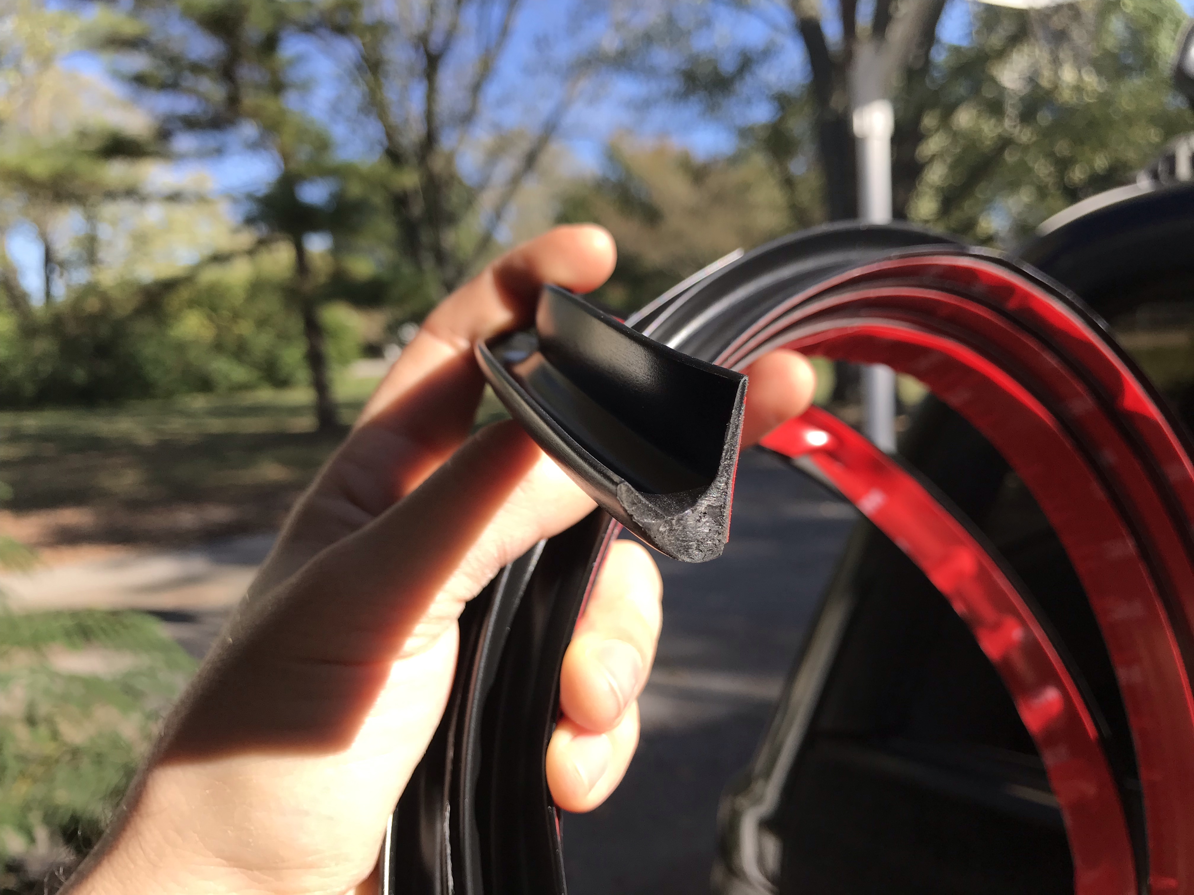
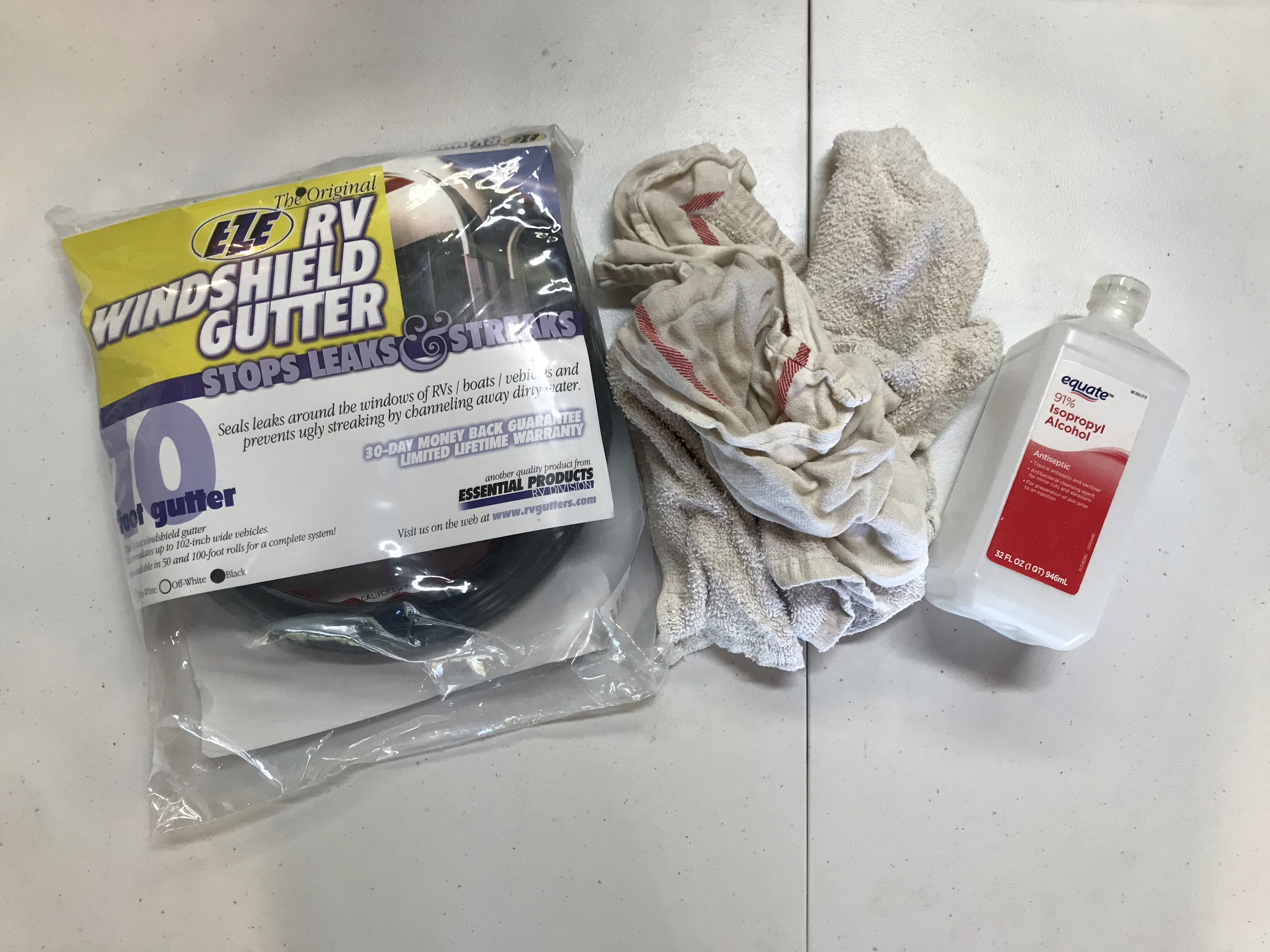
What I did find, though, was a product called RV rain gutter, which is essentially J-channel rubber molding that can be applied above windows and doors on an RV to solve this same problem.
Old toothbrush (for pressing the gutter into place)
Build
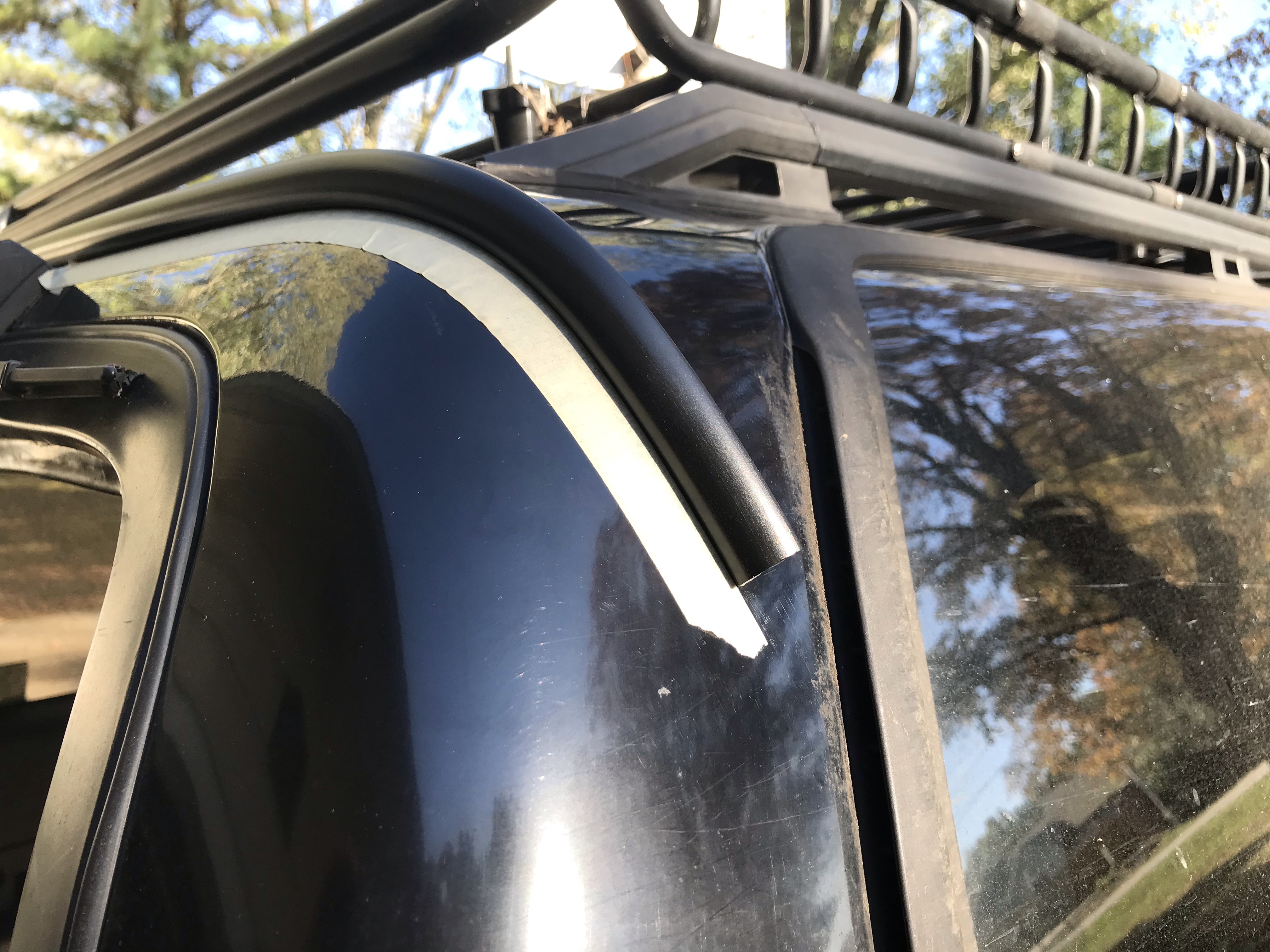
This build was really straightforward, and I basically just followed the instructions that came with the RV gutter. I cleaned the area to which I was going to apply the gutter, then rubbed it down with isopropyl alcohol and quickly dried it to get it extra clean and ready to accept the 3M adhesive strip. Then I laid out masking tape right below where I was going to put the channel.
Masking tape as a guide for the drip rail
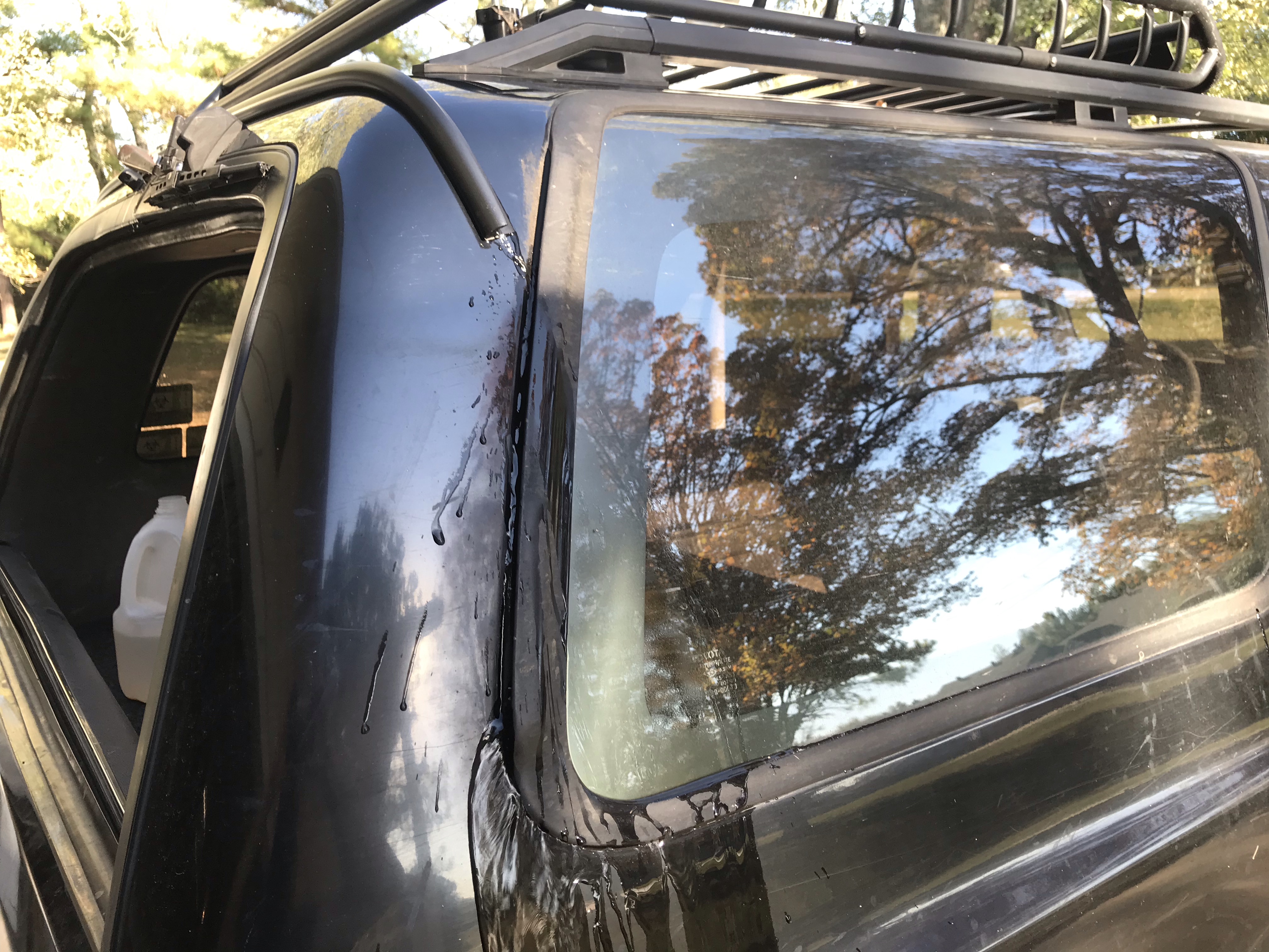
I have a window wiper assembly above my rear window, so I didn’t have a lot of room to work with, and basically mounted the drip rail immediately above the wiper. I ran the channel around the corners on either side towards the windows, where there’s a vent that handles drainage already. This gets the rain completely out of the way of the rear window and allows it to drain down the sides of the vehicle.
Look ma, no water in the back!
I tested it out by pouring a jug of water on the roof and watching it run down with the rear window open. I was very pleased that no water made it into the cargo area!
Cost
The only thing I had to buy for this project was the RV gutter itself, which was $14.74. Cheap, easy, and effective!
I’m just getting into more serious home automation and playing around with Home Assistant, and while I don’t have very many smart devices yet, I do have a cheap WiFi LED controller by Magic Home. When I first got it, I used the companion app, which was terrible, and I hated having to have separate apps for everything. As I dove into configuring Home Assistant (HA), I decided to see if there was a way to magic that controller work with HA—and it turns out, there is!
By flashing ESPHome firmware onto the controller, it becomes immediately discoverable by HA and no longer requires a separate app to manage. Now, it’s still a WiFi controller, and I don’t like the idea of saturating my WiFi network with smart devices, but I already have it so I decided to make it work.
Prep the controller for flashing
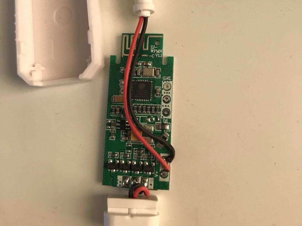
The first thing I needed to do was prep the controller to be flashed. I popped open the plastic enclosure, and identified the chip as an ESP8285, which is a version of the classic ESP8266 with 1MB of flash memory built in. This was good news and meant I should be able to flash my own firmware on it.
Magic Home WiFi LED controller opened up
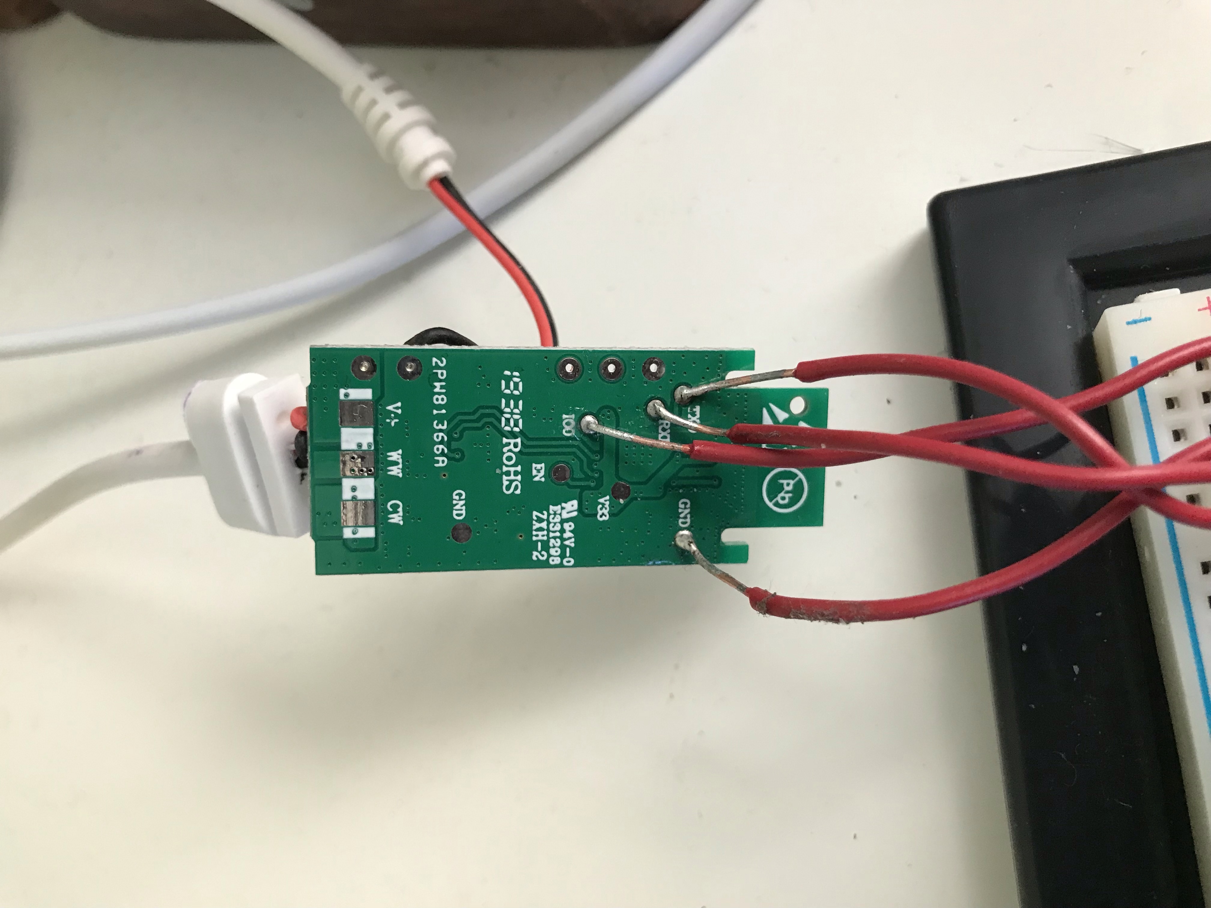
On the back of the controller were several solder pads. After scouring tutorials online, I determined the ones that I needed for this project were labeled TXD, RXD, IO0, and GND. I went ahead and soldered solid-core wire leads to each of these pads.
Leads soldered onto the Magic Home LED controller
Use an Arduino as a serial converter
Next, I needed something that could talk to the controller. You can use a USB-to-UART or USB-to-TTL cable to do this, but I didn’t have one on hand. What I do have is an Arduino Uno that doesn’t get much love, and it turns out to be a pretty simple task to turn an Arduino into a serial converter.
The Arduino has TX (transmit) and RX (receive) pins. Normally, any communication would need to go through the Arduino’s ATmega328P chip, which would involve writing a sketch and uploading it to the Arduino. However, there’s another option: you can jumper the Arduino’s RESET pin to GND (ground) and bypass the chip completely, giving you direct access to the Arduino’s USB-to-TTL converter and thus TX and RX pins over USB.
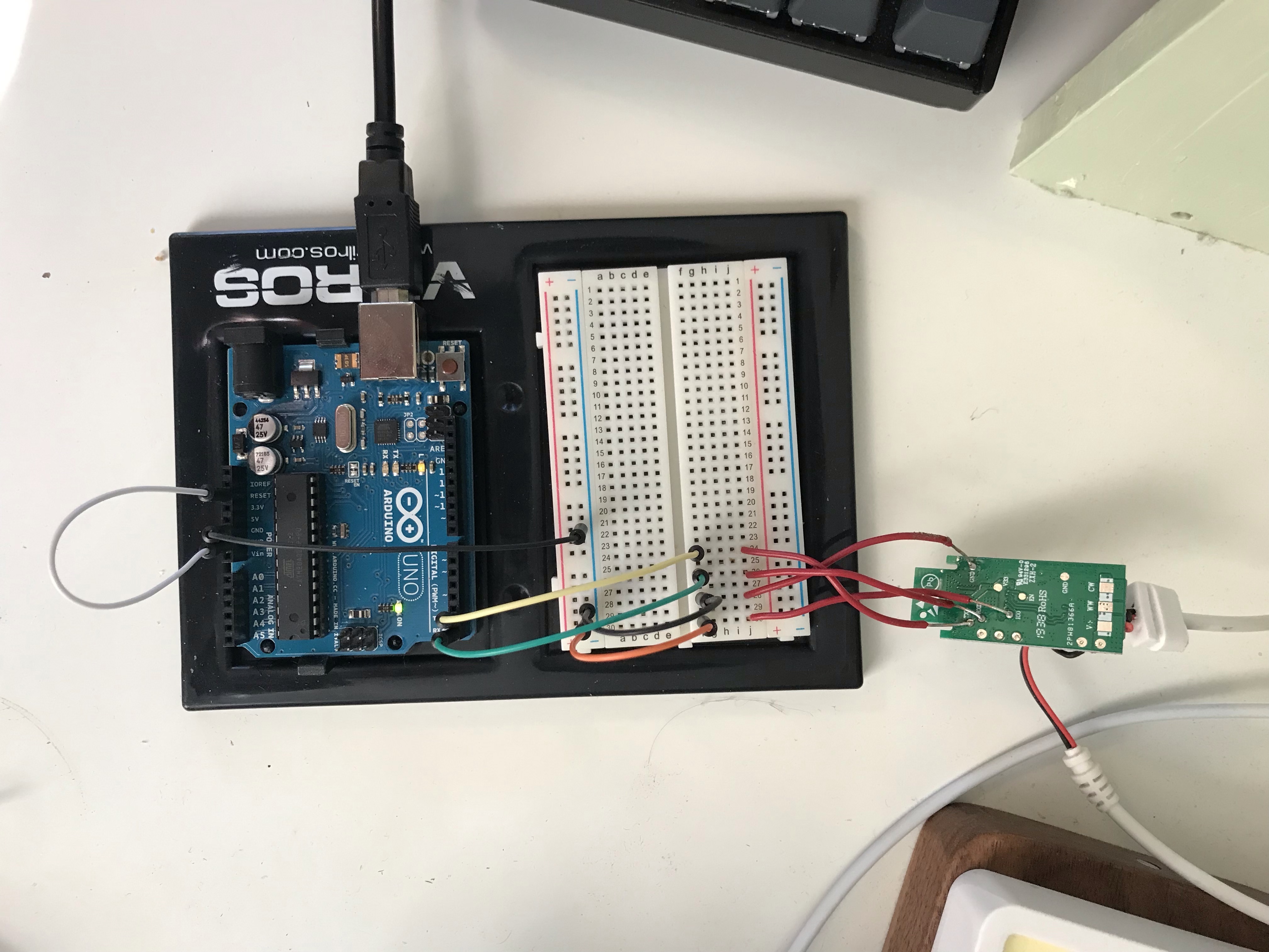
The Arduino wiring is pretty simple here. I used a breadboard to lay things out really cleanly.
JumperRESET to GND.
Run a wire from GND to the negative rail on the breadboard.
Run a wire from TX to a terminal strip on the breadboard.
Run a wire from RX to another terminal strip on the breadboard.
Run a wire from the negative rail to a 3rd terminal strip on the breadboard.
Run a second wire from the negative rail to a 4th terminal strip on the breadboard.
Arduino connected to the Magic Home LED controller
This may be a bit excessive with the breadboard, but it made it really easy to connect the leads from the controller, especially as I played around with it to get it working correctly.
A note on TX and RX serial connections
Normally, when connecting serial devices together, the TX pin of one device is connected to the RX pin of the other. This is so when the first device transmits (TX), the other device receives (RX) that transmission.
However, for this project, since I’m accessing the Arduino’s built-in USB-to-TTL converter directly instead of going through the ATmega328P chip with a sketch, I needed to connect the TX pin on the Arduino to the TXD pin on the controller instead of the RXD pin, and likewise the RX pin on the Arduino to the RXD pin.
This is because the Arduino pins are labelled from the perspective of the ATmega328P chip: a serial message would be received on the Arduino’s RX pin, which in turn is mapped to the USB-to-TTL converter’s TX pin, as in normal serial communication. Same for transmitting: the Arduino’s TX pin is mapped to the converter’s RX pin. Since we’re bypassing the ATmega328P chip completely, the Arduino’s RX pin is effectively the converter’s TX pin.
Normal operation with ATmega328P chip
USB-to-TTL converter
ATmega328P chip
Serial device
RXD
TX
RX
TXD
RX
TX
Bypass operation
USB-to-TTL converter
Arduino board
LED controller
RXD
“TX”
TXD
TXD
“RX”
RXD
Connect LED controller to Arduino
With the clean breadboard layout, it’s now a simple task to connect the LED controller to the Arduino via the breadboard. Effectively, the pins map like so:
Arduino board
LED controller
TX
TXD
RX
RXD
GND
GND
GND
IO0
The LED controller’s IO0 pin needs to be grounded for the controller to boot in “flash mode” to allow us to flash the firmware.
A note on voltages
The Arduino operates on 5V, while the LED controller operates on 3.3V. I read several tutorials that strongly recommended stepping down the voltage sent to the TXD pin on the controller from 5V to ~3.3V, but I was unable to communicate with the controller when using a voltage divider circuit. The only way I was able to make it work was using a direct connection with the full 5V. If you do this, continue at your own risk! It could damage the controller.
Build the custom firmware
To create the firmware, I used ESPHome through Home Assistant. Once ESPHome was installed as a Supervisor Add-On in HA, I went to Supervisor → Dashboard → ESPHome → Open web UI and clicked the + button to add a new “node”.
I gave it a name and WiFi information so it could connect to my home network, and selected ESP8266 as the ESP device.
Once the node is created, I clicked Edit to edit the YAML. It should already have the basics, and I only needed to add the following snippet at the end to be able to control the LED strip. Note that my controller and strip are only for single-color LEDs; you can set this up for RGB LEDs too with a little more configuration. ESPHome has lots of documentation.
# Define the light component
light:
  - platform: monochromatic
    name: "Monitor Backlight"
    output: output_component1

# Define the output to control the LEDs
output:
  - platform: esp8266_pwm
    id: output_component1
    pin: GPIO12
The real key piece in that snippet is the last line: pin: GPIO12. This tells the firmware to use IO pin 12 to control the LED strip, which I managed to find documented here. There are other Magic Home models on that site as well. For RGB LEDs, for example, you would need to control 3 pins.
Once I edited the YAML, I clicked Save and then Install. Since I’m manually flashing the firmware over USB, I selected Manual download, which compiles and downloads a .bin (binary) file with custom firmware generated from the YAML.
Flash the firmware to the controller
All the pieces are coming together now! The last step is to actually flash the new custom firmware onto the LED controller. Start with everything disconnected from power. Plug the USB cable into the Arduino and computer. Then, plug the LED controller into its power source. With the IO0 pin grounded, it should boot up in flash mode and be ready to receive the firmware.
I used esptool.py to flash the firmware. It’s developed by Espressif, the same company that makes the ESP8266 chip. I’m on a Mac, so I used these steps to install and run it using Terminal.
The documentation states that the flash should be erased before writing in order for it to be successful. However, I didn’t find that to be the case. I was able to write only without erasing, and it ran successfully.
The --port /dev/tty.usbmodem14101 options specifies which serial port to use. The value should match what you found by running ls /dev/tty.usb* in the previous step.
The -fm dout option tells it to use the “dual output” flash mode. There are other modes described here which I did not try, but this mode worked for me.
The 0x00000 option tells it to write the firmware starting at the very first memory address.
The monitor-backlight.bin is the name of the firmware file that was compiled and downloaded by ESPHome. I ran this command from the same folder the file was in, but you may need to provide a path to the file here rather than just the filename.
If everything works successfully, you should see output similar to this:
esptool.py v3.1
Serial port /dev/tty.usbmodem14101
Connecting...
Failed to get PID of a device on /dev/tty.usbmodem14101, using standard reset sequence.
.
Detecting chip type... ESP8266
Chip is ESP8285N08
Features: WiFi, Embedded Flash
Crystal is 26MHz
MAC: d8:f1:5b:a2:9c:9a
Uploading stub...
Running stub...
Stub running...
Configuring flash size...
Flash will be erased from 0x00000000 to 0x00065fff...
Compressed 417792 bytes to 290846...
Wrote 417792 bytes (290846 compressed) at 0x00000000 in 25.3 seconds (effective 132.2 kbit/s)...
Hash of data verified.

Leaving...
Hard resetting via RTS pin...
Test the controller
After a successful flash, disconnect the LED controller from power, disconnect the Arduino, and remove the LED controller leads from the breadboard. Connect the controller to power again and to the LED strip.
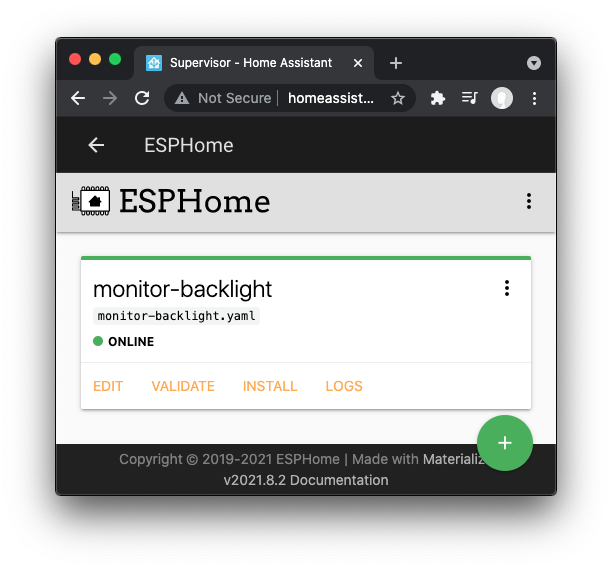
If the firmware was configured properly, you should be able to go to Supervisor → Dashboard → ESPHome → Open web UI and see the device come online in a few seconds automatically
Magic Home LED controller connected to ESPHome in Home Assistant
That’s it! The LED controller is now available to be added as an integration in Home Assistant, and then a card can be added to the dashboard to control it. I used a button card to turn it on and off, and I added automations to turn it on and off and set it to different brightnesses.
Recently, the rear window on my 2nd gen 4Runner started intermittently not rolling down. Pretty soon, it was intermittently working and usually didn’t work at all. When it worked, it worked great, but when it didn’t, nothing happened, so I knew it wasn’t the window motor. Since I could hear the rear window relay click when I turned the key in the tailgate, I suspected the contacts had worn out and the relays needed to be replaced.
(If you’re diagnosing rear window issues, 4Crawler has a great troubleshooting page that I found really helpful. It’s geared toward 1st gen 4runners, but most of it is applicable to 2nd gens as well.)
I had actually already replaced the rear window relays about 3 years ago, but I used some cheap Chinese relays from Amazon that weren’t built to last. This time I ordered 4 Panasonic relays from DigiKey. They’re a drop-in replacement for the original relays and are rated for 10A instead of 6A so they should last quite a bit longer.
2 relays removed, 2 of the cheap Chinese relays in blue, and the 2 original larger relays at the bottom (never replaced).
This is a cheap fix to a common problem. I only paid $12.66 for these high-quality relays from DigiKey, half of which was shipping, and I already had all the tools. If you have to buy a soldering iron, solder, and flux, you might spend $30 or $40 total.
Accessing the Relay Box
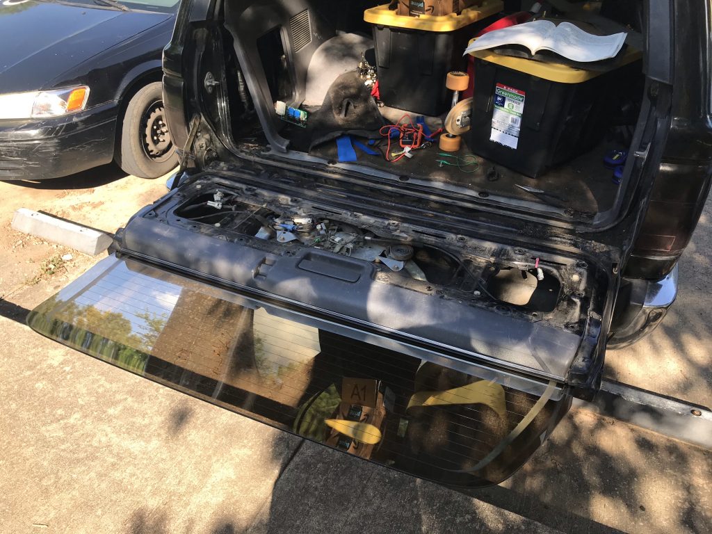
The first problem was that my window was rolled up, and I needed to open the tailgate to get to the relay box. To solve this, I ran jumper cables from the battery into the cargo area, popped off the tailgate panel inside, and used some alligator clip jumpers from the jumper cables to the pins on the rear window motor plug to roll the window down. Kind of a pain, but it worked!
With the tailgate open, I pulled off the trim along the bottom edge of the cargo area, and then pulled back the driver side quarter panel trim, just enough to access the bolts holding the relay box to the body. The relay box unplugs from the connector and then there are 3 enclosure pieces that pop off in order to slide the circuit board out.
You can see the quarter panel trim pulled back to access the relay box.
Replacing the Relays
Once I had the circuit board free, I warmed up my solder sucker, dabbed a little flux on the joints, and proceeded to remove the solder from the old relays.
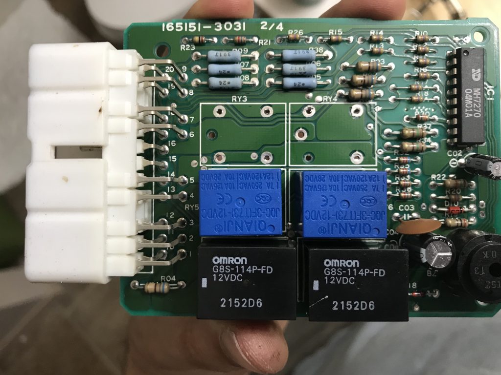
You’ll notice on the circuit board that the relays are labeled. By examining the wiring diagram and doing some probing on the circuit board, I worked out the following:
RY3 is the window up relay
RY4 is the window down relay
RY5 and RY6 appear to be for the rear washer
RY1 and RY2 appear to be for the rear wiper
I went ahead and replaced RY3, RY4, RY5, and RY6 since they were all the same cheap relays I had replaced before. If you’re only having problems with the window itself, you can probably get away with just replacing RY3 and RY4.
I highly recommend a solder sucker, desoldering iron, wick, or braid to remove the old relays. It’s not necessary, but it makes the process a lot faster and cleaner. Flux isn’t necessary either, but it helps.
With the solder removed, the old relays should pop out pretty easily with a little wiggling.
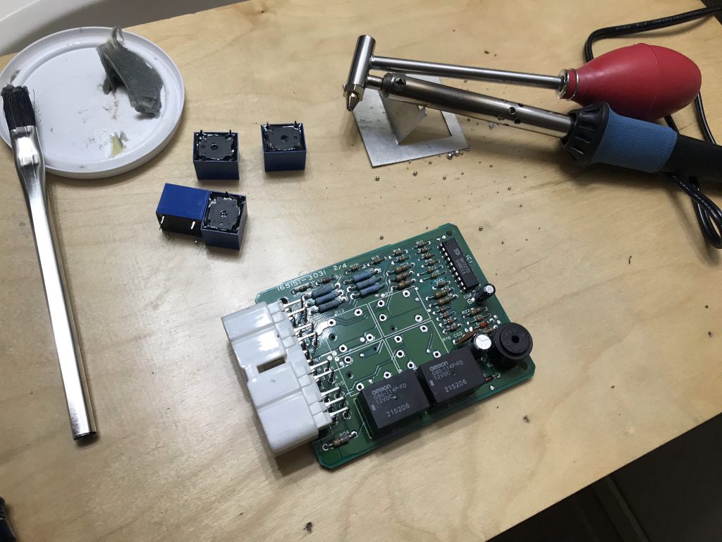
Old relays removed from the circuit board using my solder sucker.
The new relays fit snugly in the holes, so I didn’t end up needing a third hand. I had to re-tin my soldering iron but then I was able to quickly solder the pins to the board.
Be sure to use proper technique when soldering on the circuit board, since it is easy to damage the board. Make sure the soldering iron is clean and properly tinned first. Then get a bit of solder on the end of the iron, hold the relay pin in place, and touch the soldering iron to both the pad on the board and the pin. The solder should flow onto both the pad and the pin to make a solid connection. Let it cool without moving the pin, then move onto the next pin.
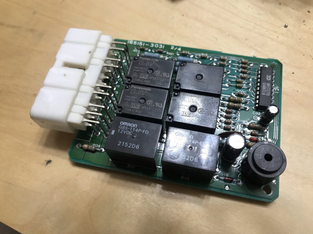
New relays installed on the circuit board.
With the new rear window relays installed, reinstall the relay box and test out the rear window. If the relays were the problem as they were on mine, it should be working like new now!
Switch Mod
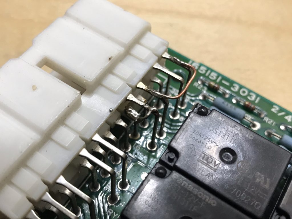
While I had the circuit board out, I took the opportunity to do the switch mod that allows me to roll down the rear window using the switch in the center console without having the key in the ignition. Since using the key in the tailgate doesn’t require the ignition switch, it’s simply a matter of jumping the pins used for the tailgate switch to the pins used for the console switch.
For the 2nd gen 4runner, the following pins are jumped:
I chose to jump the pins on the top of the circuit board by soldering some copper wire across the connector leads, but it was pretty tricky to solder pin 17 this way. Alternatively, you could jump the pins on the bottom of the circuit board where the connector isn’t in the way.
This mod worked great and really makes it easier to access the back without using my key at all. It also sets me up to install a future mod: an additional rear window switch located in the cargo area, so I can easily roll down the rear window if I’m sleeping in the back.
Bonus: Tailgate Access
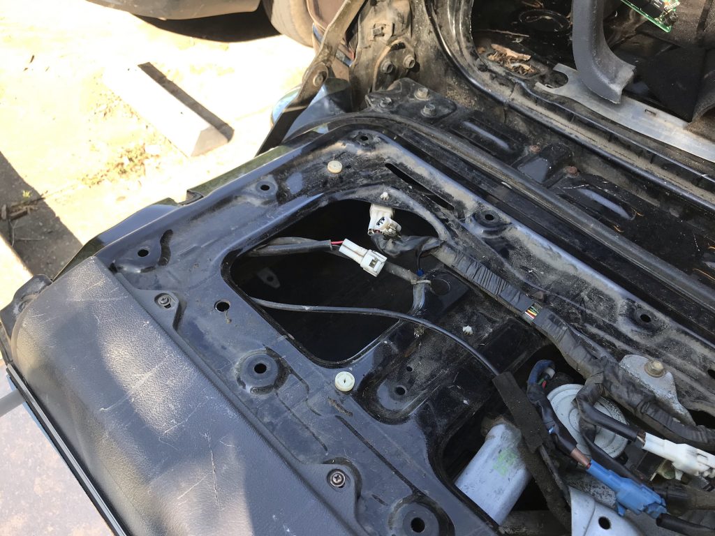
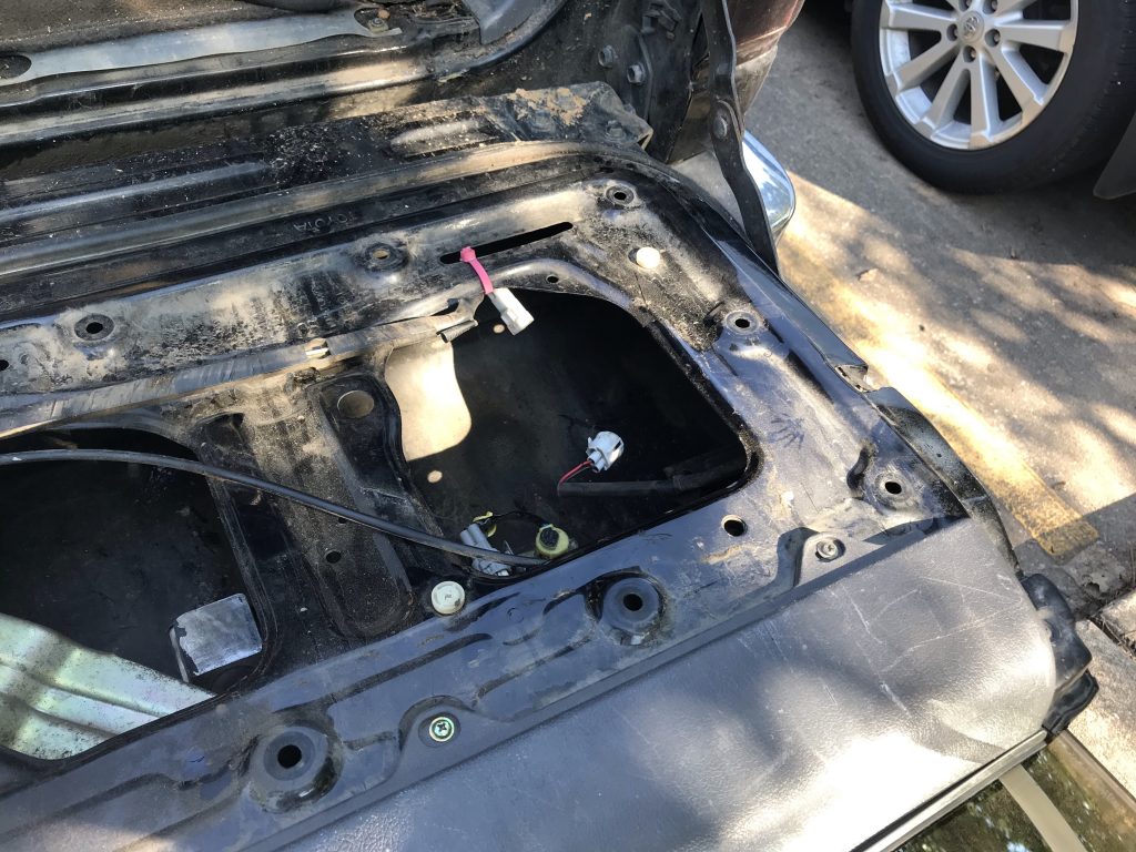
As an aside, once you have your rear window working, if you need to roll it up to access the guts of the tailgate while it’s open, you can disconnect the 2 rear window lock switches located on either side of the tailgate, and then roll the window up with the switch. This is handy for accessing the key switch in the tailgate from the inside. Careful not to roll it up too far, though!
Driver side rear window lock switch disconnectedPassenger side rear window lock switch disconnected