Tag: DIY

  • Poor Man’s MoonShade

    Last weekend, we attended Rendezvous in the Ozarks for the second year in a row. It was rainy the first couple of days, so we brought along a 10’ x 10’ canopy to give us cover between our ground tent and the back of the 4Runner. But man! that thing is heavy and bulky.

    So when we got back from camping, I started looking into alternatives. There are lighter-weight canopies out there, and also a really cool product called the MoonShade, which is basically a fancy lightweight vehicle awning. But I’m overlanding on a budget, and $325 is a bit steep for an awning. Enter the DIY Poor Man’s MoonShade.

    This build pairs well with my Rear Window Drip Rail.

    The basic concept consists of a tarp with one side affixed to the vehicle and the opposite side supported by 2 poles. Since I want this to come off the back of the 4Runner, and it’s pretty narrow, I also need a strut to hold the tarp out wider than the 4Runner, similar to the MoonShade’s solution. I also want to run guy lines from the corners to help keep it taut.

    Supplies
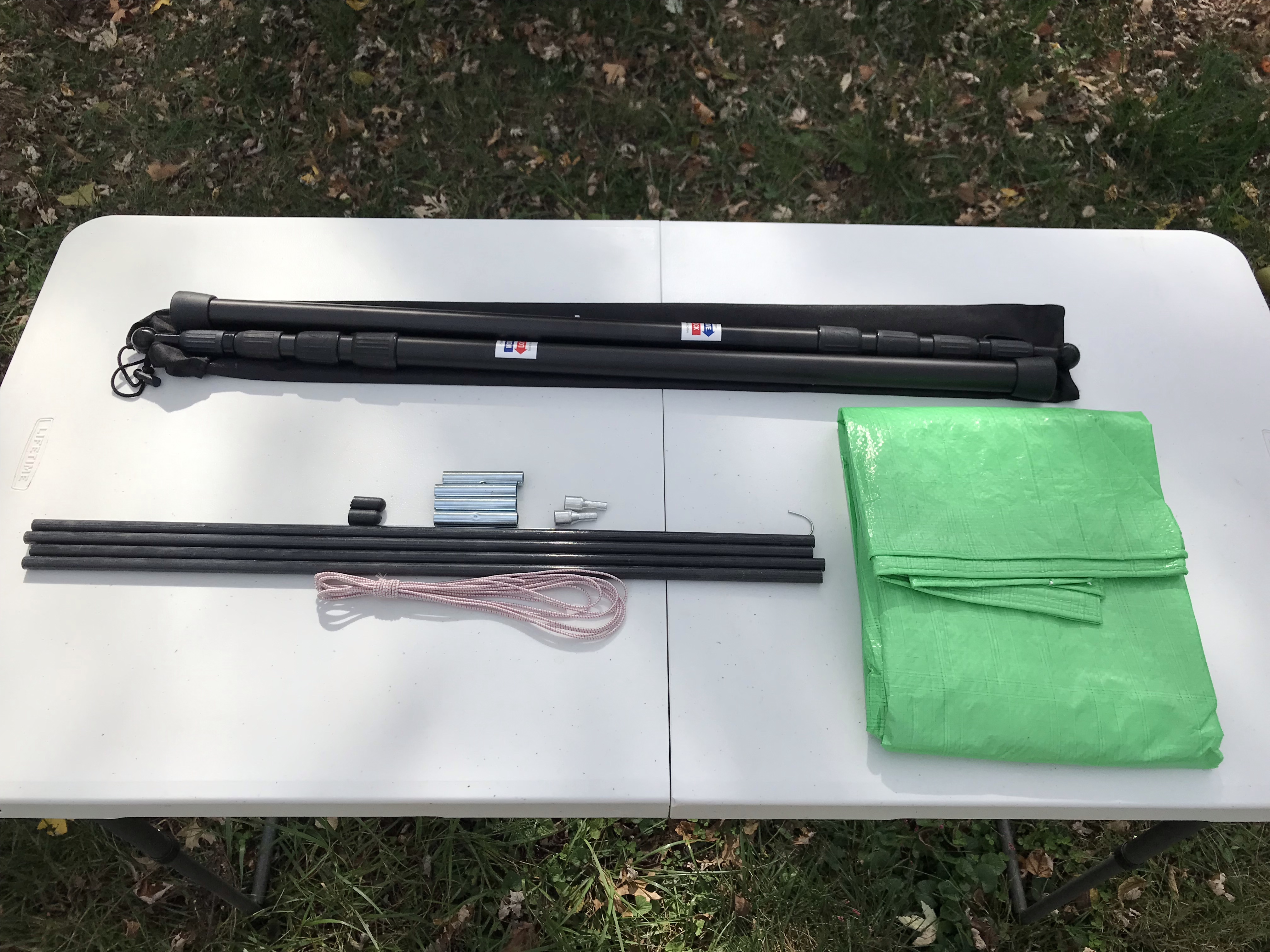
    Supplies for the awning
    Supplies for the awning

    The nice thing about fully adjustable tent poles is that you can set up one slightly taller than the other, or both shorter than the vehicle, to create a slope to shed rain.

    The tent pole repair kit was the key piece to this puzzle for me. I was having trouble finding a double-ended tent pole with 2 pins for the grommets like the MoonShade has, and was seriously considering fabricating something myself until I stumbled across this kit with enough poles and pieces to make exactly what I needed.

    Build

    The main thing that needed to be built was the strut. I assembled the tent pole pieces and laid them out on the 8’ side of the tarp, with the pin end in one of the grommets, and set the other pin end in the opposite grommet to see where to cut the last tent pole section, marking it with a pencil.
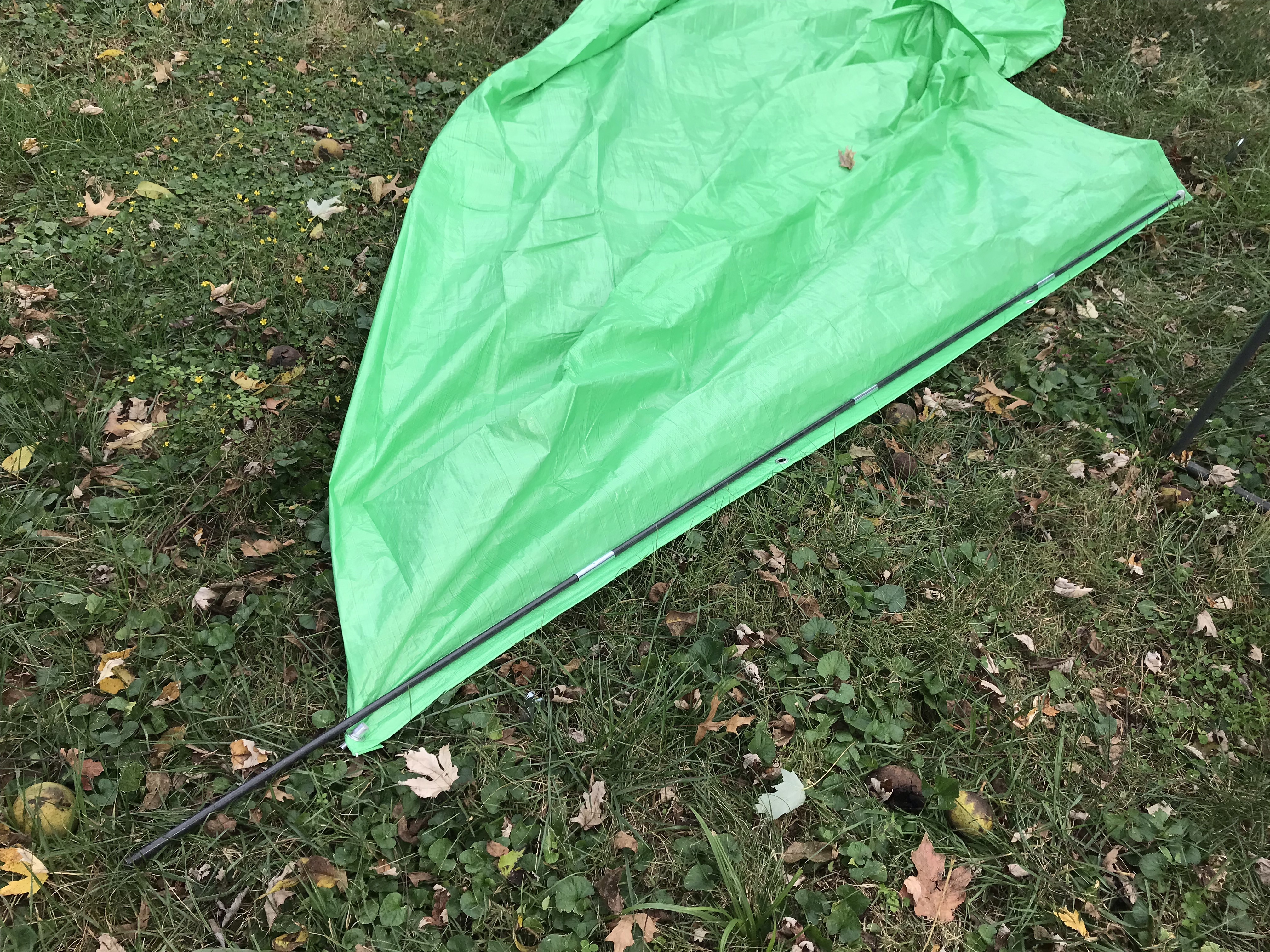
    Measuring to cut the fiberglass tent pole
    Measuring to cut the fiberglass tent pole

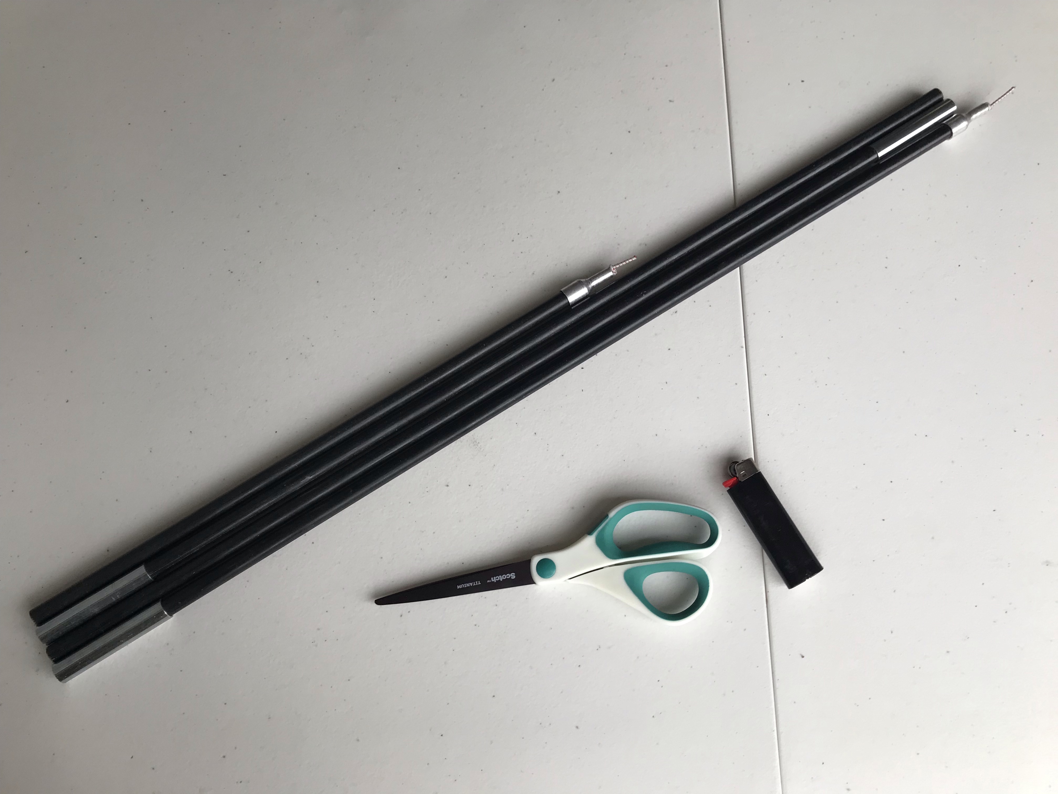
    Then I cut the tent pole section with a hacksaw, sanded the cut end, and fully assembled the tent pole with the provided shock cord. I tied the shock cord after the pin ends so the whole assembly is contained, and melted the ends of the shock cord to keep it from fraying.
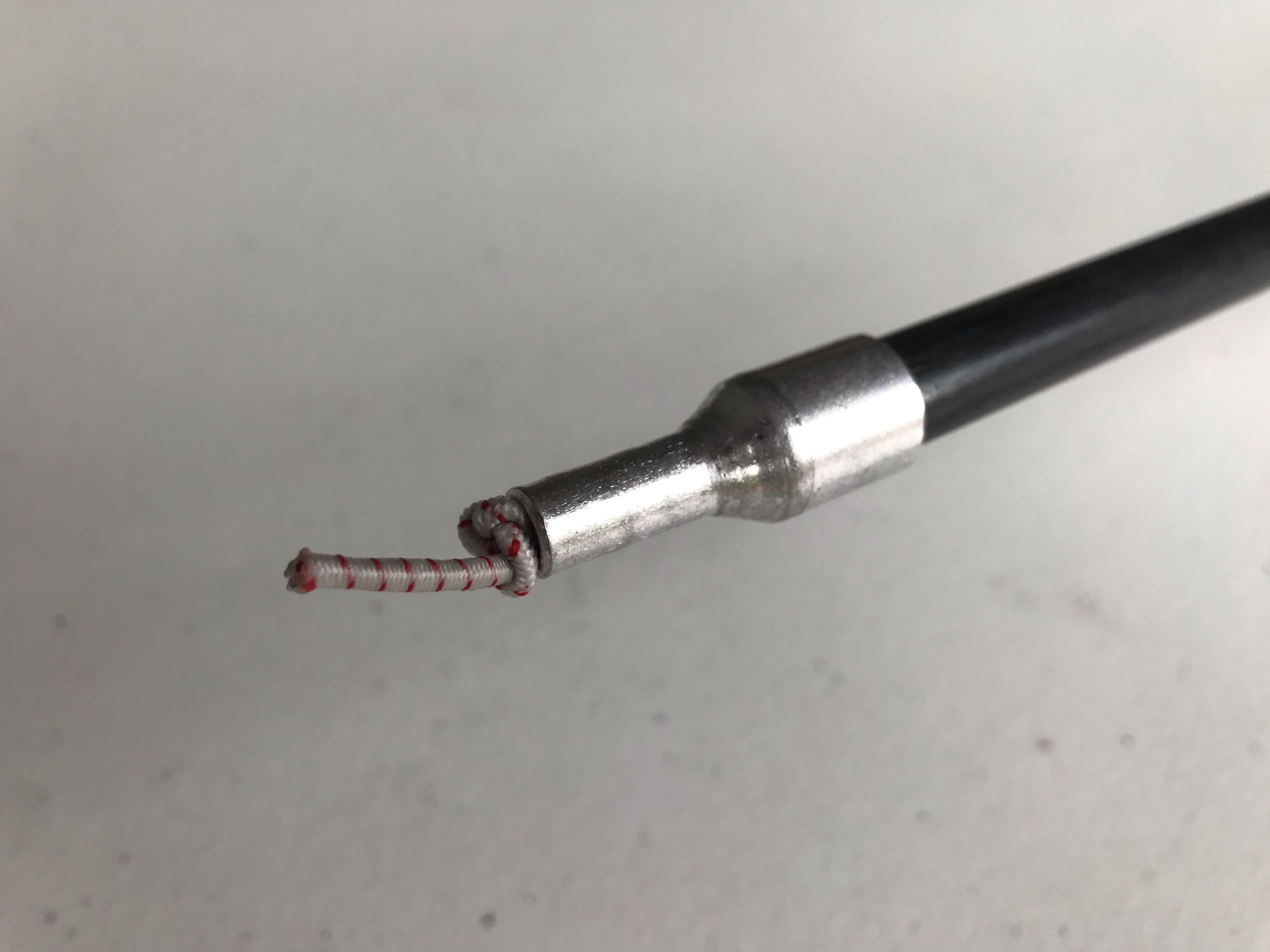
    Shock cord tied after the pin end
    Shock cord tied after the pin end
    The completed strut for the Poor Man's MoonShade
    The completed strut

    I also needed a way to affix the strut to my vehicle. MoonShade offers a variety of attachment methods, but since I have a roof rack, I kept it simple and used a couple of tarp ball bungees to hold the strut to the roof rack. In my case, the tarp grommets lined up pretty close to the sides of my roof rack, so I loop the ball bungees through those as well to hold everything together.
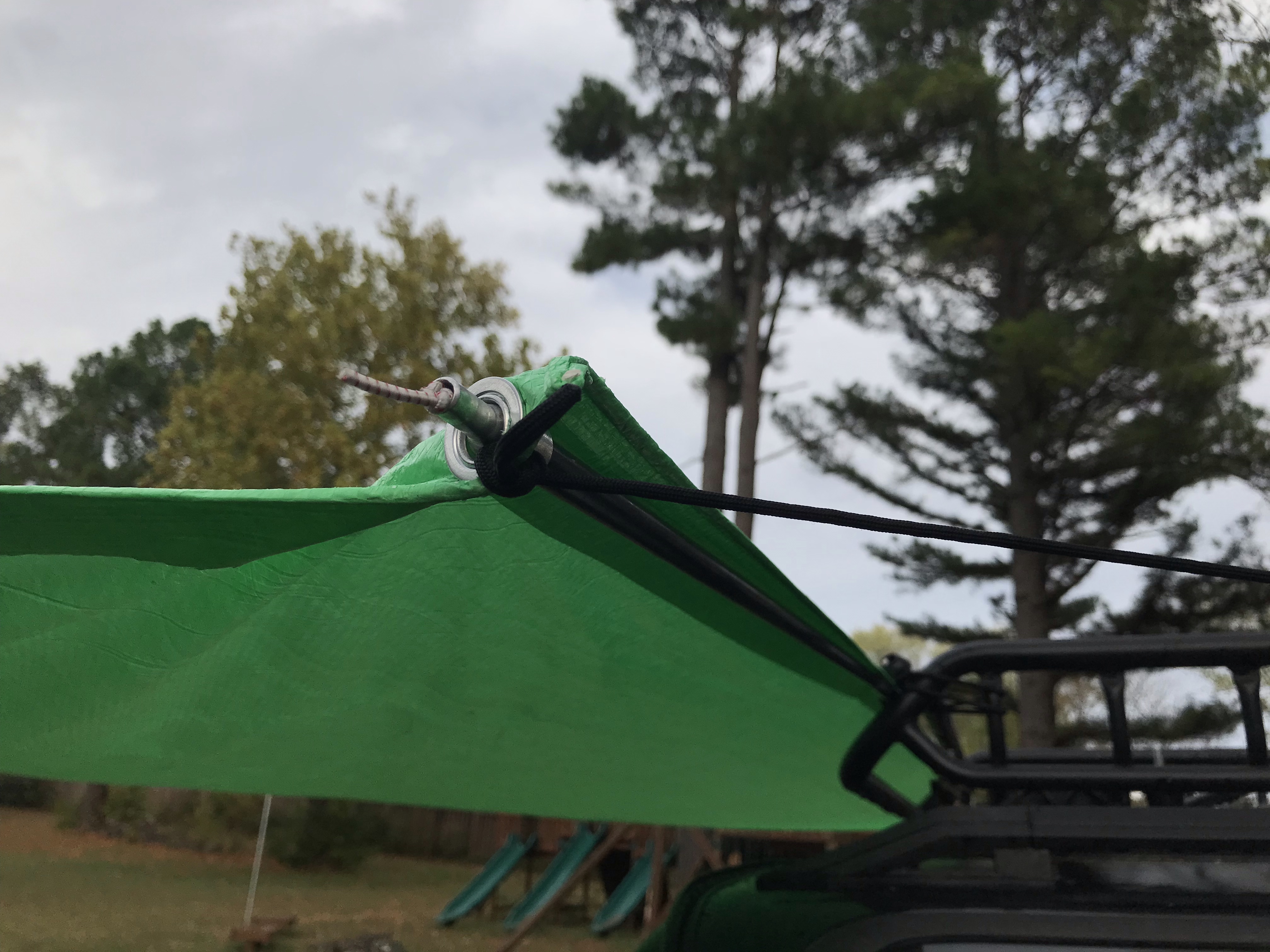
    Detail showing strut, guy line to roof rack, and ball bungee holding strut to roof rack
    Ball bungee in the background holding the strut and tarp to the roof rack

    The last piece is the guy lines. I measured out paracord with enough length to tie taut-line hitches for adjustability and tied them permanently to all 4 corners of the tarp. On the vehicle side, I actually attached these to my roof rack with carabiners, but they’re long enough I could stake them to the ground instead.
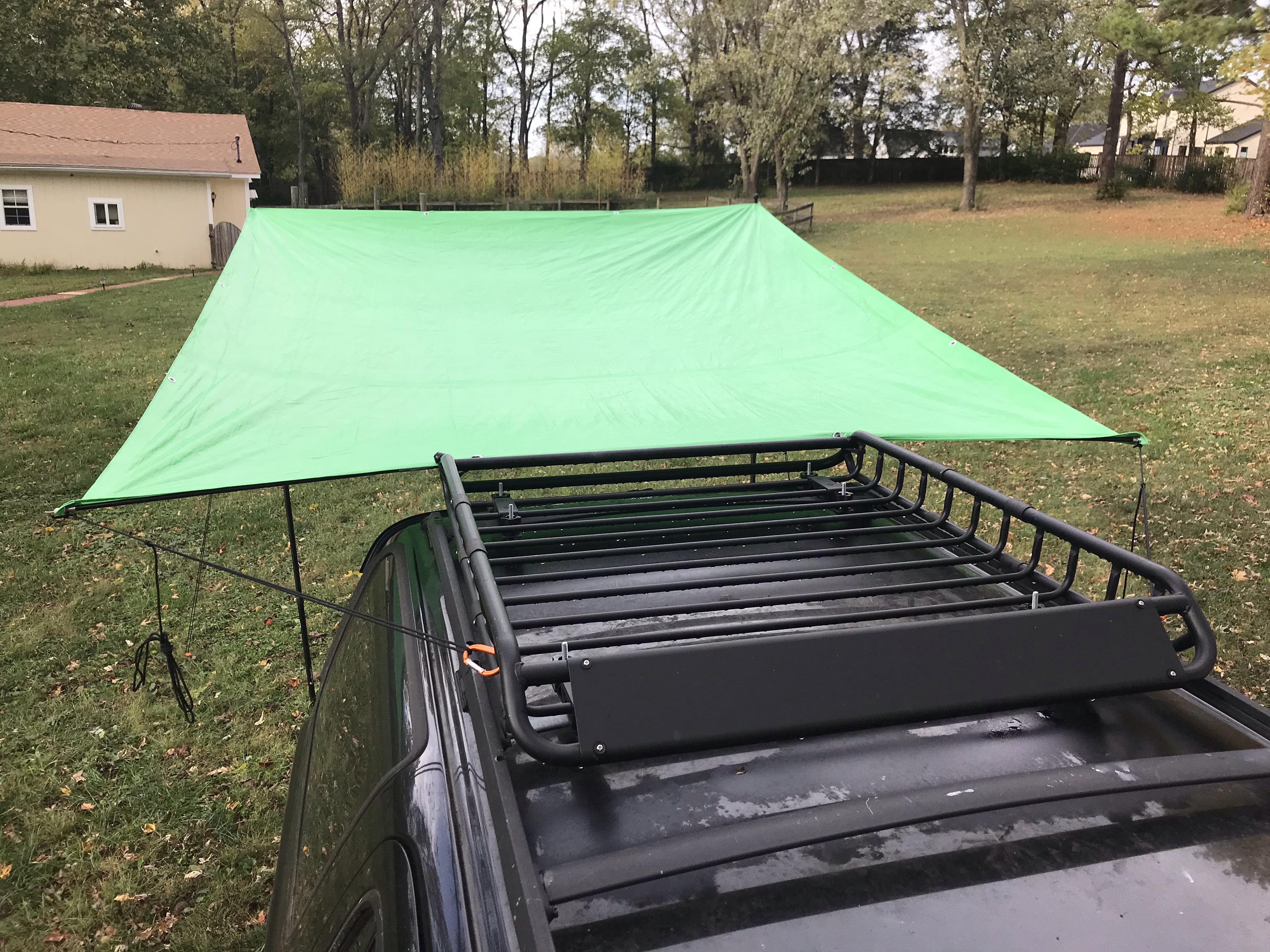
    Guy lines attached to the roof rack
    Guy lines attached to the roof rack

    The far side is supported by the telescoping tarp poles and held taut with guy lines staked to the ground.
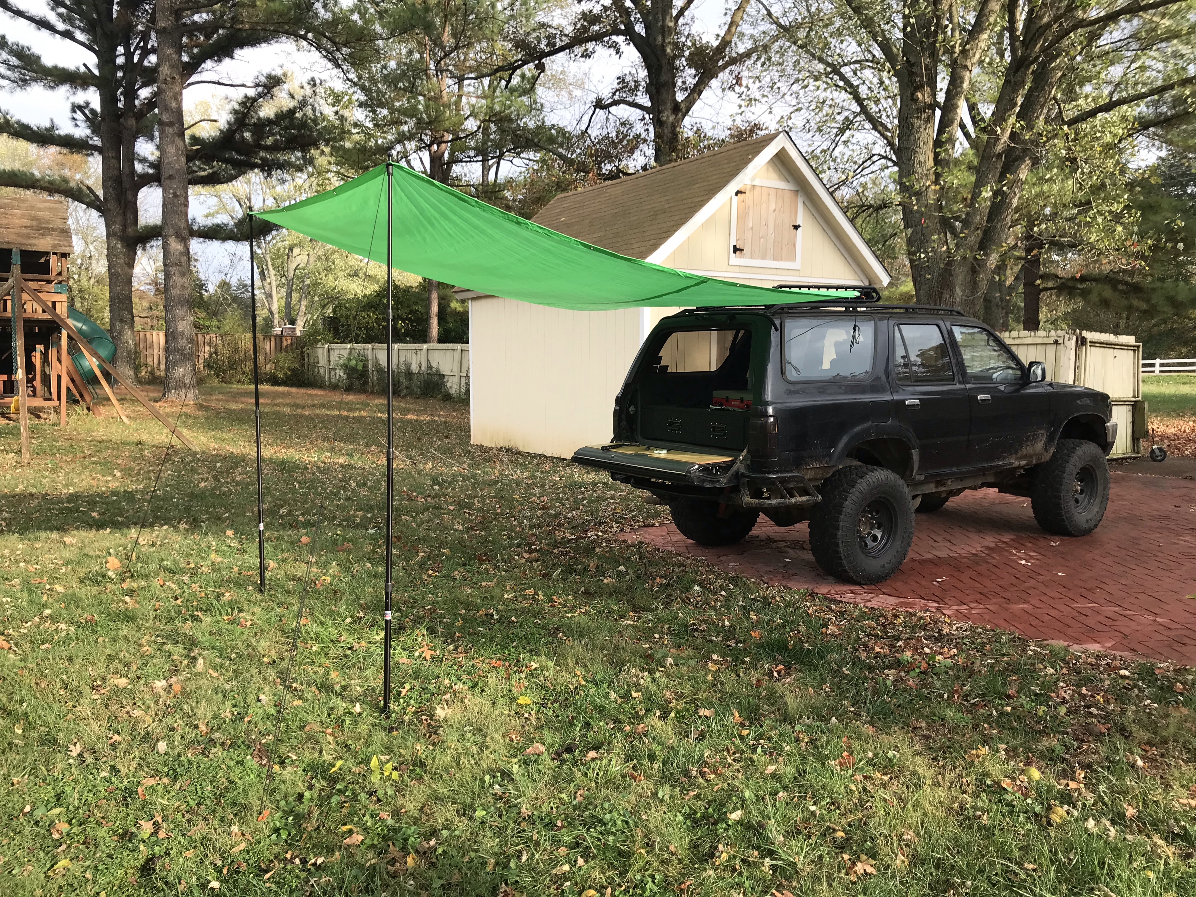
    The Poor Man's MoonShade
    The Poor Man’s MoonShade

    I need to play around with tensioning to make sure water doesn’t pool in the center, but overall, I’m really happy with this build. It’s easier to set up with 2 people, but I can tear it down by myself in just a couple of minutes, which is a lot faster than my 10’ x 10’ pop-up canopy!

    Cost

    I managed to pull this off for under $100.

    • Tarp: $14.99
    • Adjustable tarp poles: $54.99
    • Tent pole repair kit: $16.99
    • Tent stakes: $6.49
    • Carabiners: $2.87

    Total: $96.33
  • Spoofing Automatic Transmission Solenoids

    Spoofing Automatic Transmission Solenoids

    When I swapped a 3.4 engine and ECU into my 4Runner, the donor vehicle had an automatic transmission, and the ECU expected to see signals from the automatic transmission solenoids. Without those signals, it would illuminate the check engine light, masking any real issues I may need to investigate. To avoid that, the signals can be spoofed or simulated using resistors. All that’s needed is a little wiring and soldering.

    Supplies

    • (3) 15 ohm power resistor, rated for 25W or higher
    • (1) 5 ohm power resistor, rated for 50W or higher
    • 18-20 AWG wire
    • Project box or mounting surface

    Tools

    • Wire cutters/strippers
    • Soldering iron and solder

    Pinout

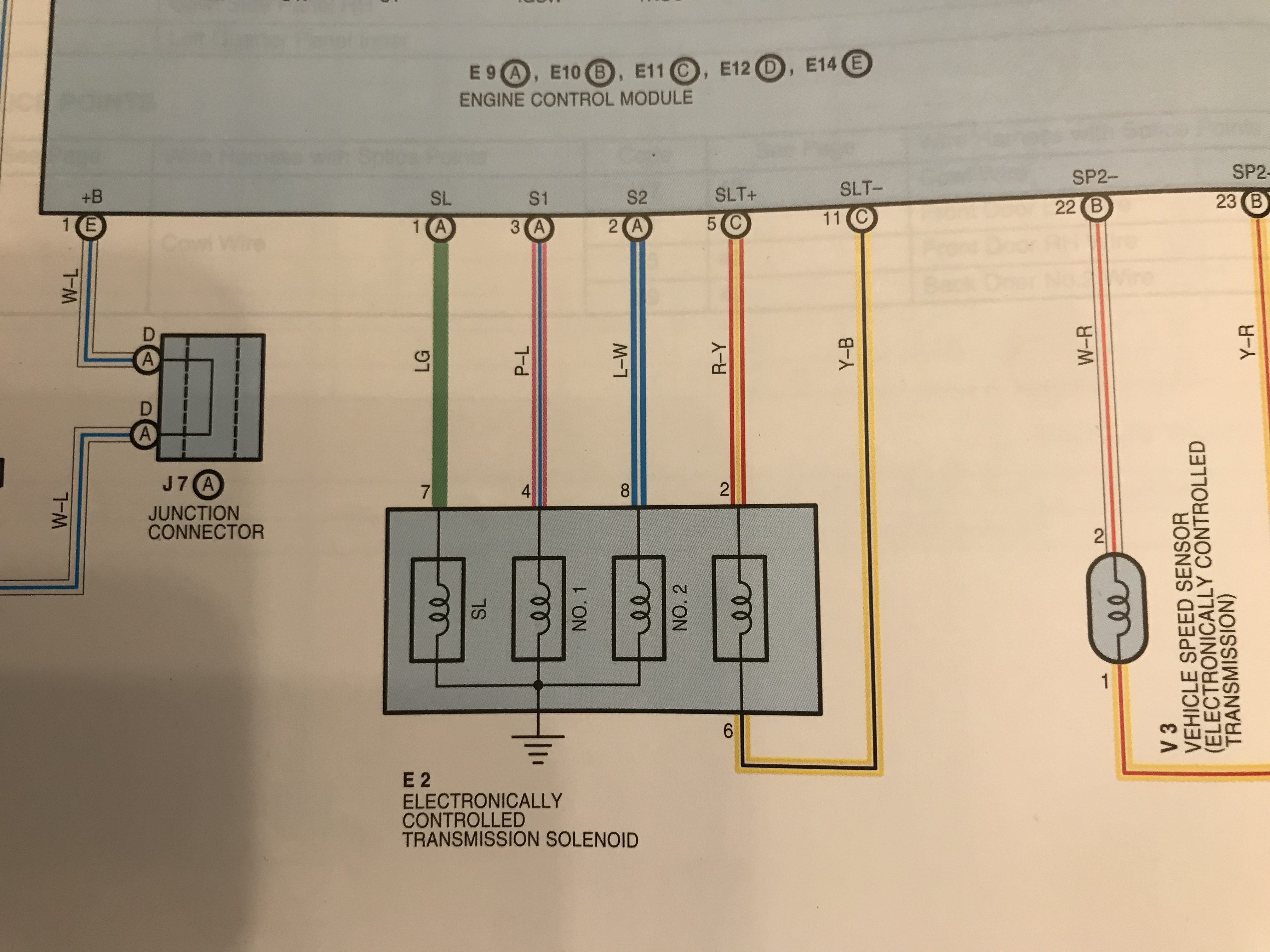
    A 3rd gen 4runner auto ECU will have 5 pins for the Electronically Controlled Transmission (ECT) Solenoid. In a 2002 4runner, these pins are as follows:

    • SL (Connector E9 Pin 1, LG)
    • S1 (Connector E9 Pin 3, P-L)
    • S2 (Connector E9 Pin 2, L-W)
    • SLT+ (Connector E11 Pin 5, R-Y)
    • SLT- (Connector E11 Pin 11, Y-B)
    Diagram for 2002 4Runner with automatic transmission
    Diagram for 2002 4Runner with automatic transmission

    The SL, S1, and S2 wires all go through the solenoids to ground. The SLT+ wire goes through the solenoid and back to the ECU to the SLT- pin.

    You will need to look at the Electronic Wiring Diagram (EWD) for your 3.4 engine’s model year and confirm the ECU pin locations and wire colors because they vary by year.

    Theory

    Each solenoid has a range of resistance and voltage that the computer expects to see.

    The SL, No. 1, and No. 2 solenoids all have a resistance of 11–15 ohms, and range in voltage from < 1.5 V to 9–14 V, depending on which gear the auto transmission is currently in. Using the formula I = V / R, we can therefore calculate the maximum wattage as 14 V / 11 ohms = 17.8 W. To be safe, I rounded this up to be able to dissipate at least 25 W of power.

    The SLT solenoid has a resistance of 5.0–5.6 ohms, and pulses between < 1.5 V and 10–12 V when the engine is idling. Consequently, we can calculate the maximum wattage as 12 V / 5 ohms = 28.8 W. I rounded this up to safely dissipate at least 50 W of power.

    Based on this information, we can use 3 power resistors rated for 15 ohms and 25 W to spoof the SL, No. 1, and No. 2 solenoids, and we can use 1 power resistor rated for 5 ohms and 50 W to spoof the SLT solenoid.

    Build

    Essentially all that needs to be done is soldering wires to the resistors and then connecting the wires to the ECU and ground accordingly.

    The wires to the ECU connectors should ideally be joined with a lineman splice to the connector wires and then soldered. This will create a very strong connection to avoid signal interruption to the ECU. Optionally, instead of a direct splice, the wires can be crimped and soldered to terminals or a multi-pin connector so that the simulator can be easily removed from the ECU.

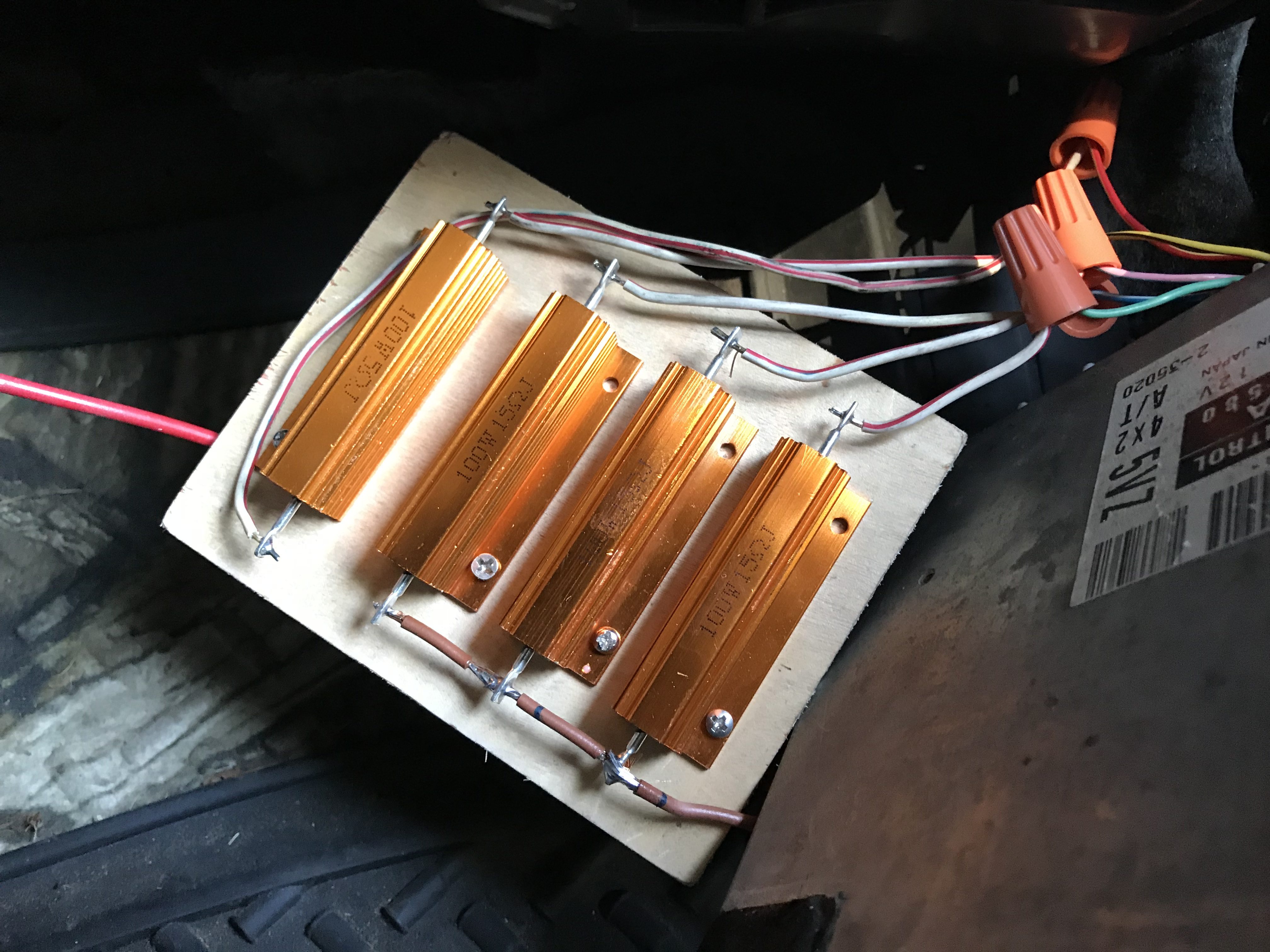
    Prototype of the simulator
    Prototype of the simulator. Notice how the brown ground wires are chained together at the bottom. The wire nuts are very temporary and shouldn’t be used long-term!

    There are 2 options for the ground wire coming from 3 of the resistors:

    1. Run it directly to a bolt on the chassis for a direct ground
    2. Splice it into the ground wire coming from the ECU

    I opted for option 2 to keep everything ECU-related contained and not have another ground point to worry about.

    Testing

    Once everything is wired up and the simulator is connected to the ECU and properly grounded, then the ECU should no longer through a Diagnostic Trouble Code (DTC) related to the automatic transmission solenoids. You may need an OBD-II port connected to your ECU to verify this, but if this was the only issue causing the check engine light to illuminate, then the check engine light should no longer be on!

    Cost

    This was a pretty cheap fix. I only needed to buy the power resistors, and was able to use wires and hardware I already had on hand.

    • 15 ohm power resistors: $15.60
    • 5 ohm power resistor: $7.70
    • Scrap wires: free
    • Wood mounting plate: free
    • Wire nuts: free

    Total cost: $23.30

    I’m planning to revisit this mod in the near future to tidy it up and move it to the engine bay. The resistors still get pretty toasty, so I’ve slipped the whole assembly into an old coffee can that sits on the passenger floorboard for now so my wife doesn’t burn her foot!

  • Rear Window Drip Rail

    One of the (few) flaws of the 2nd gen 4runner, in my opinion, is the lack of a drip rail above the rear window. Even if the rear of the vehicle is under cover (such as my Poor Man’s MoonShade), if the rear window is open, rain on the roof will run straight into the cargo area!

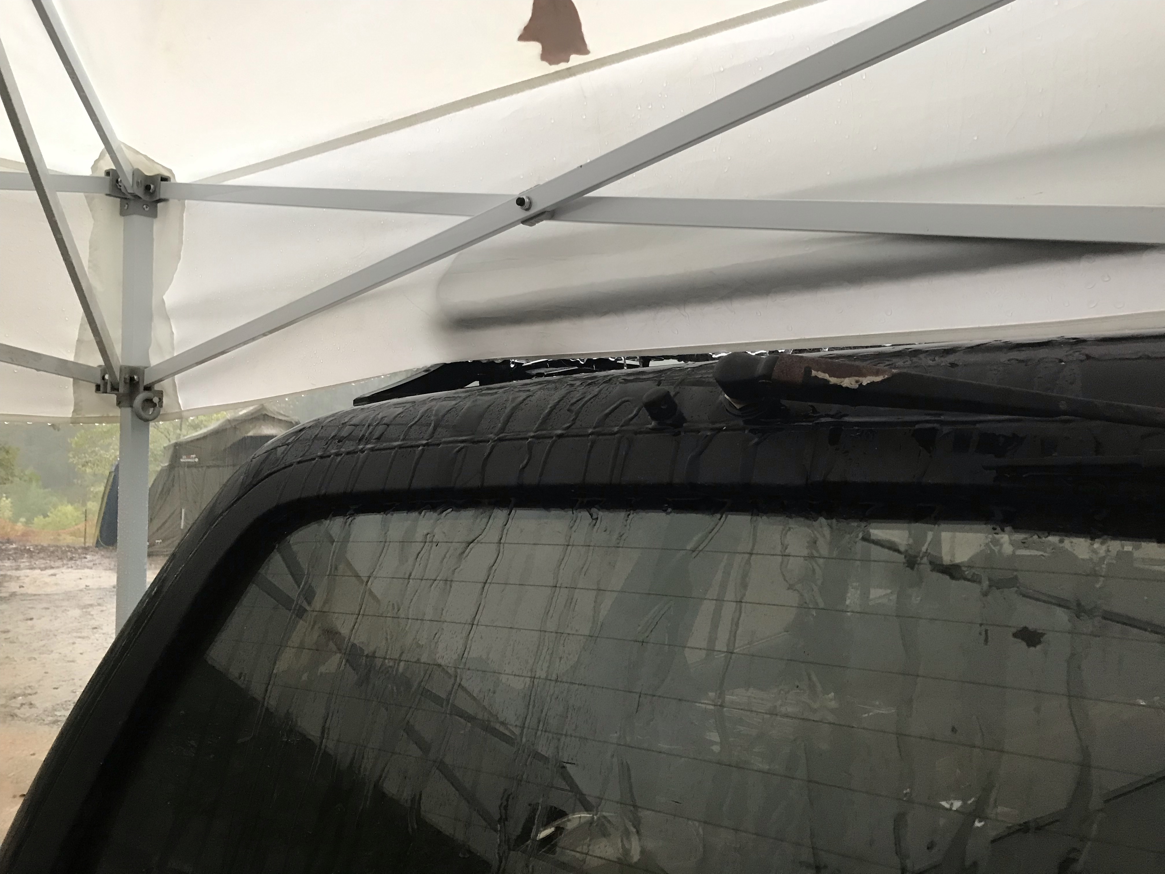
    Rear window under cover with rain streaks
    I should be able to open the rear window under cover without getting rain in the back!

    I spent several hours trying to find someone else who had solved this problem before, and maybe my Google-fu is getting rusty, but I was surprised that I couldn’t find anyone else doing something about this!

    I think the ideal long-term solution would be to weld a proper drip rail above the window, but I don’t have a welder, and I’m not prepared to strip and repaint. Maybe someday…

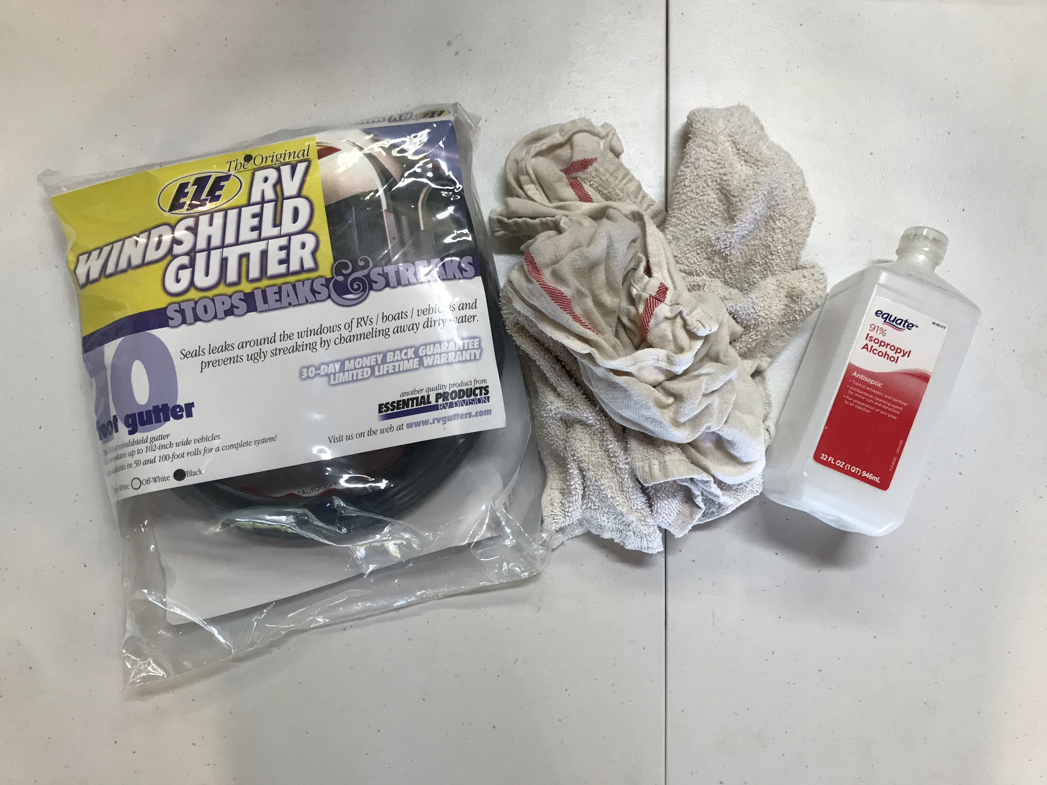
    What I did find, though, was a product called RV rain gutter, which is essentially J-channel rubber molding that can be applied above windows and doors on an RV to solve this same problem.

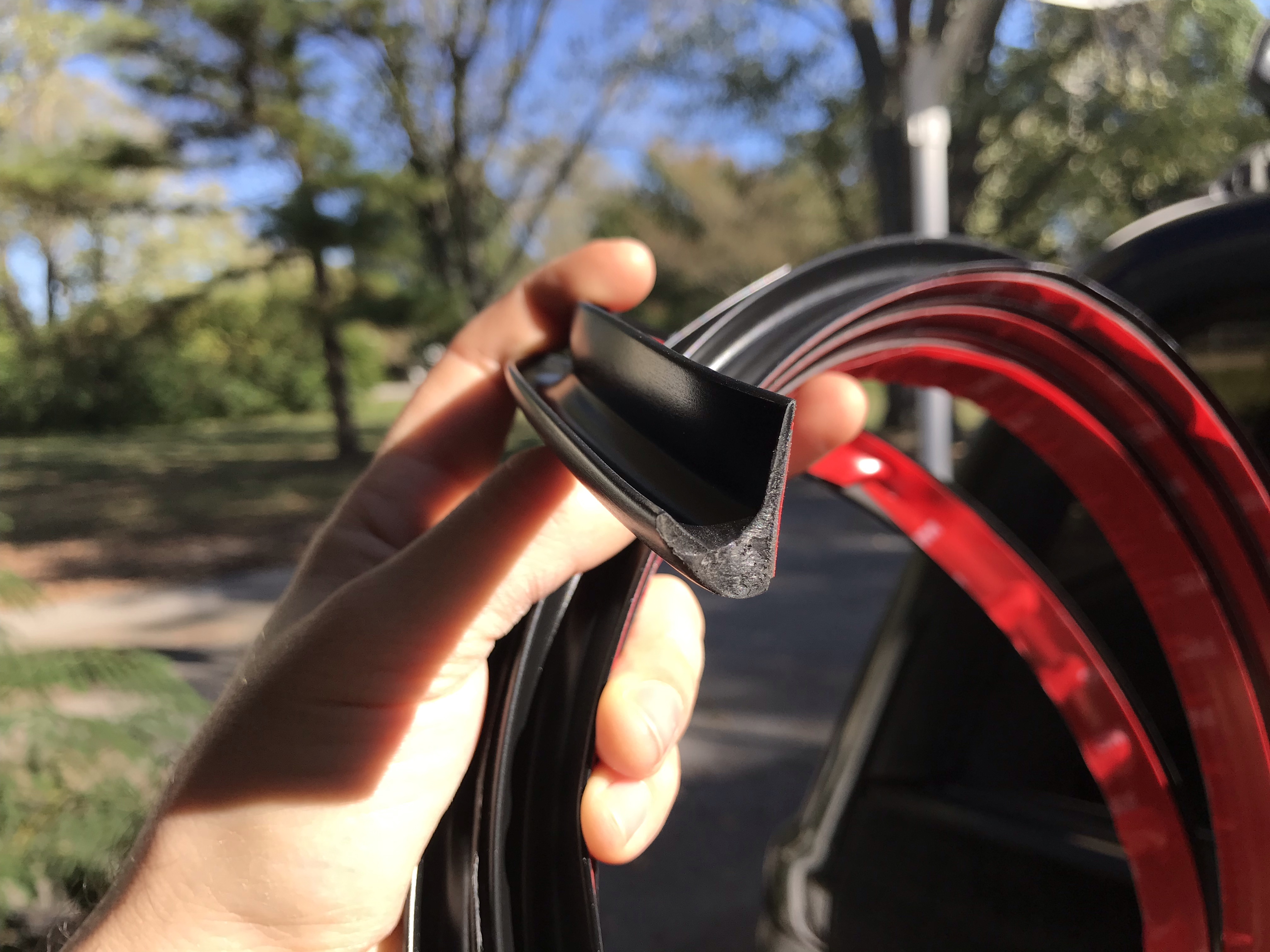
    RV rain gutter used as rear window drip rail
    Look at that nice J shape

    Supplies

    RV gutter, rags, and isopropyl alcohol
    Mis en place
    • RV gutter (I bought 10′ but I used about 52″)
    • Rags
    • Isopropyl alcohol
    • Masking tape (optional but recommended)
    • Old toothbrush (for pressing the gutter into place)

    Build

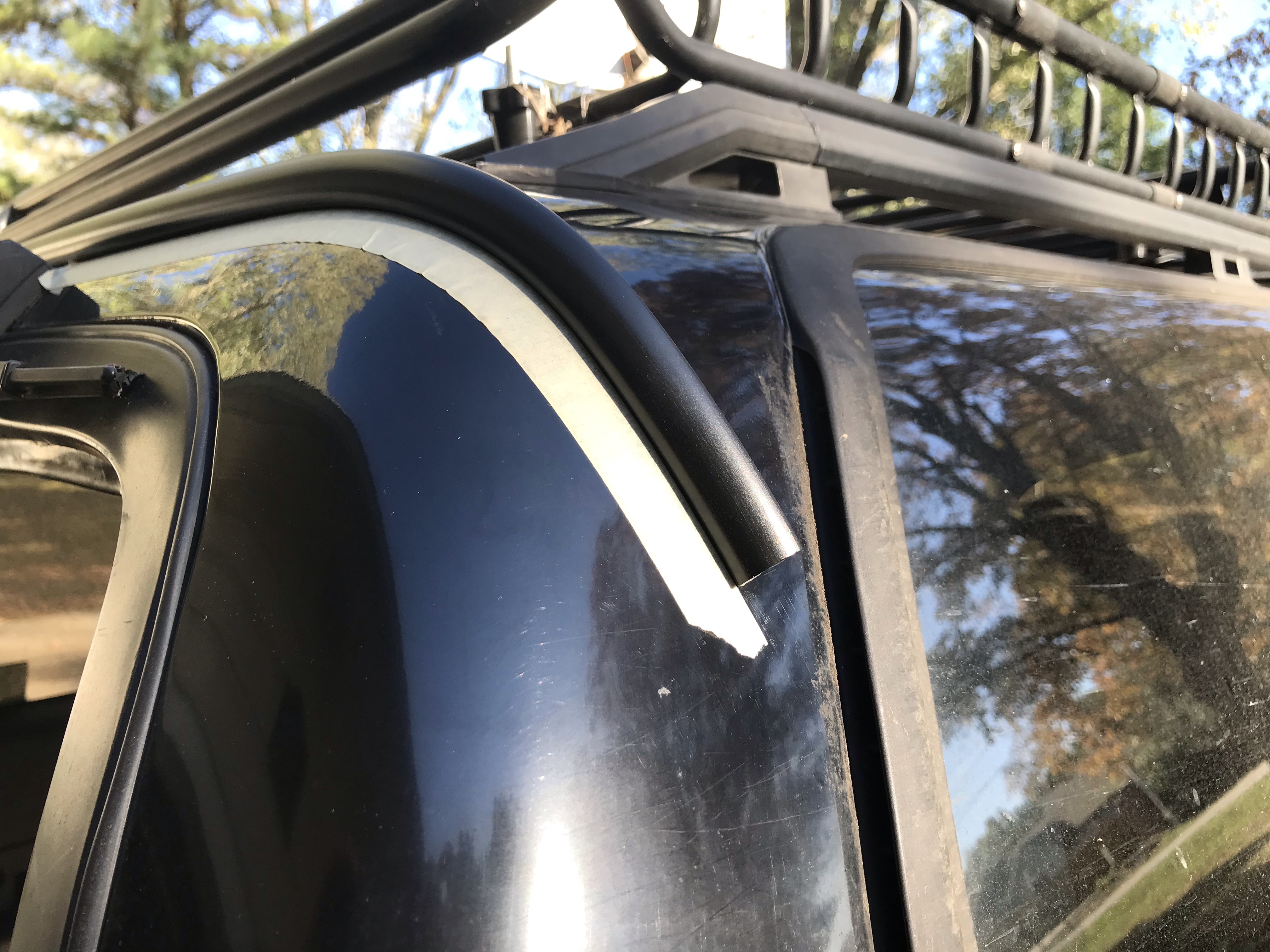
    This build was really straightforward, and I basically just followed the instructions that came with the RV gutter. I cleaned the area to which I was going to apply the gutter, then rubbed it down with isopropyl alcohol and quickly dried it to get it extra clean and ready to accept the 3M adhesive strip. Then I laid out masking tape right below where I was going to put the channel.

    Masking tape as a guide for the rear window drip rail
    Masking tape as a guide for the drip rail

    I have a window wiper assembly above my rear window, so I didn’t have a lot of room to work with, and basically mounted the drip rail immediately above the wiper. I ran the channel around the corners on either side towards the windows, where there’s a vent that handles drainage already. This gets the rain completely out of the way of the rear window and allows it to drain down the sides of the vehicle.

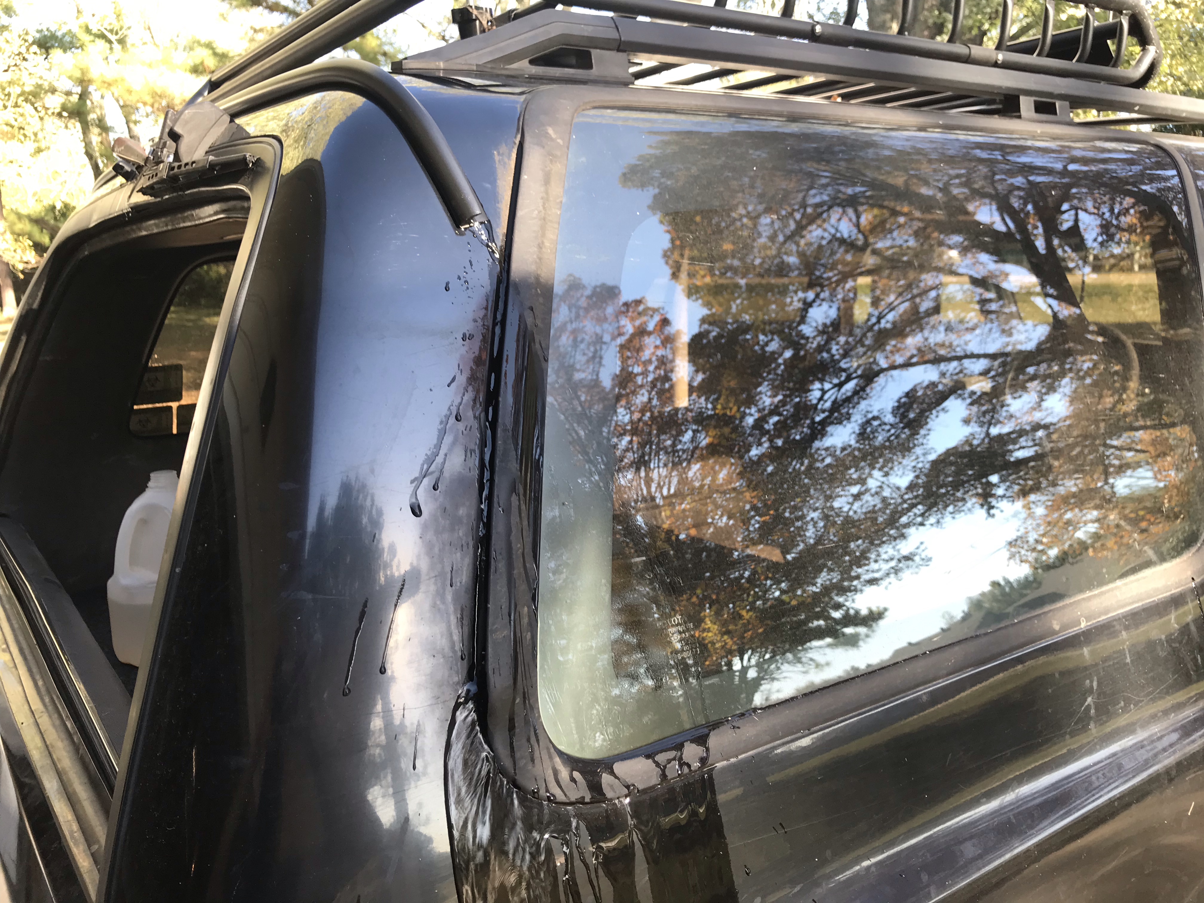
    Testing the rear window drip rail
    Look ma, no water in the back!

    I tested it out by pouring a jug of water on the roof and watching it run down with the rear window open. I was very pleased that no water made it into the cargo area!

    Cost

    The only thing I had to buy for this project was the RV gutter itself, which was $14.74. Cheap, easy, and effective!