When I swapped a 3.4 engine and ECU into my 4Runner, the donor vehicle had an automatic transmission, and the ECU expected to see signals from the automatic transmission solenoids. Without those signals, it would illuminate the check engine light, masking any real issues I may need to investigate. To avoid that, the signals can be spoofed or simulated using resistors. All that’s needed is a little wiring and soldering.
Supplies
- (3) 15 ohm power resistor, rated for 25W or higher
- (1) 5 ohm power resistor, rated for 50W or higher
- 18-20 AWG wire
- Project box or mounting surface
Tools
- Wire cutters/strippers
- Soldering iron and solder
Pinout
A 3rd gen 4runner auto ECU will have 5 pins for the Electronically Controlled Transmission (ECT) Solenoid. In a 2002 4runner, these pins are as follows:
- SL (Connector E9 Pin 1, LG)
- S1 (Connector E9 Pin 3, P-L)
- S2 (Connector E9 Pin 2, L-W)
- SLT+ (Connector E11 Pin 5, R-Y)
- SLT- (Connector E11 Pin 11, Y-B)
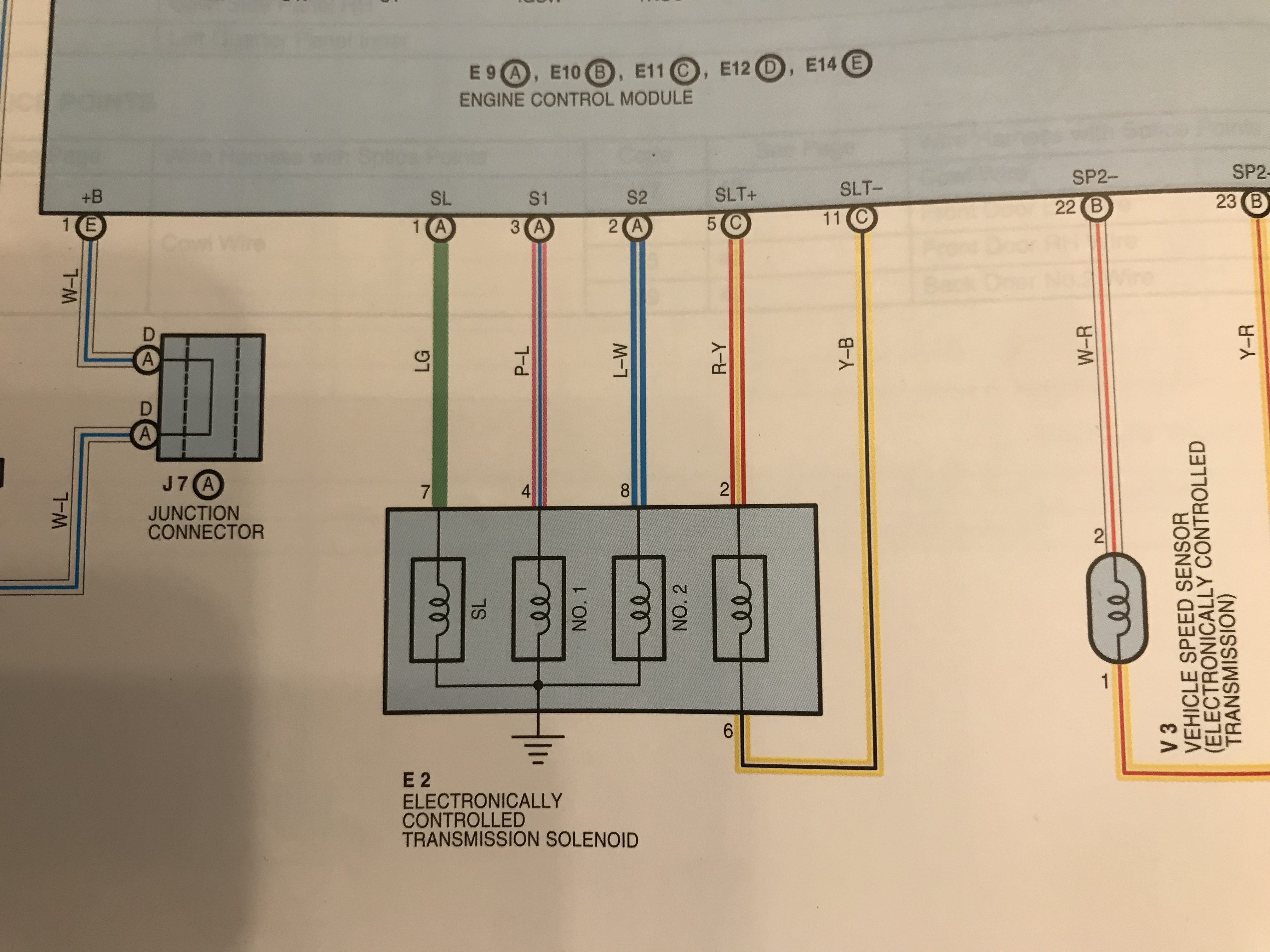
The SL, S1, and S2 wires all go through the solenoids to ground. The SLT+ wire goes through the solenoid and back to the ECU to the SLT- pin.
You will need to look at the Electronic Wiring Diagram (EWD) for your 3.4 engine’s model year and confirm the ECU pin locations and wire colors because they vary by year.
Theory
Each solenoid has a range of resistance and voltage that the computer expects to see.
The SL, No. 1, and No. 2 solenoids all have a resistance of 11–15 ohms, and range in voltage from < 1.5 V to 9–14 V, depending on which gear the auto transmission is currently in. Using the formula I = V / R, we can therefore calculate the maximum wattage as 14 V / 11 ohms = 17.8 W. To be safe, I rounded this up to be able to dissipate at least 25 W of power.
The SLT solenoid has a resistance of 5.0–5.6 ohms, and pulses between < 1.5 V and 10–12 V when the engine is idling. Consequently, we can calculate the maximum wattage as 12 V / 5 ohms = 28.8 W. I rounded this up to safely dissipate at least 50 W of power.
Based on this information, we can use 3 power resistors rated for 15 ohms and 25 W to spoof the SL, No. 1, and No. 2 solenoids, and we can use 1 power resistor rated for 5 ohms and 50 W to spoof the SLT solenoid.
Build
Essentially all that needs to be done is soldering wires to the resistors and then connecting the wires to the ECU and ground accordingly.
The wires to the ECU connectors should ideally be joined with a lineman splice to the connector wires and then soldered. This will create a very strong connection to avoid signal interruption to the ECU. Optionally, instead of a direct splice, the wires can be crimped and soldered to terminals or a multi-pin connector so that the simulator can be easily removed from the ECU.
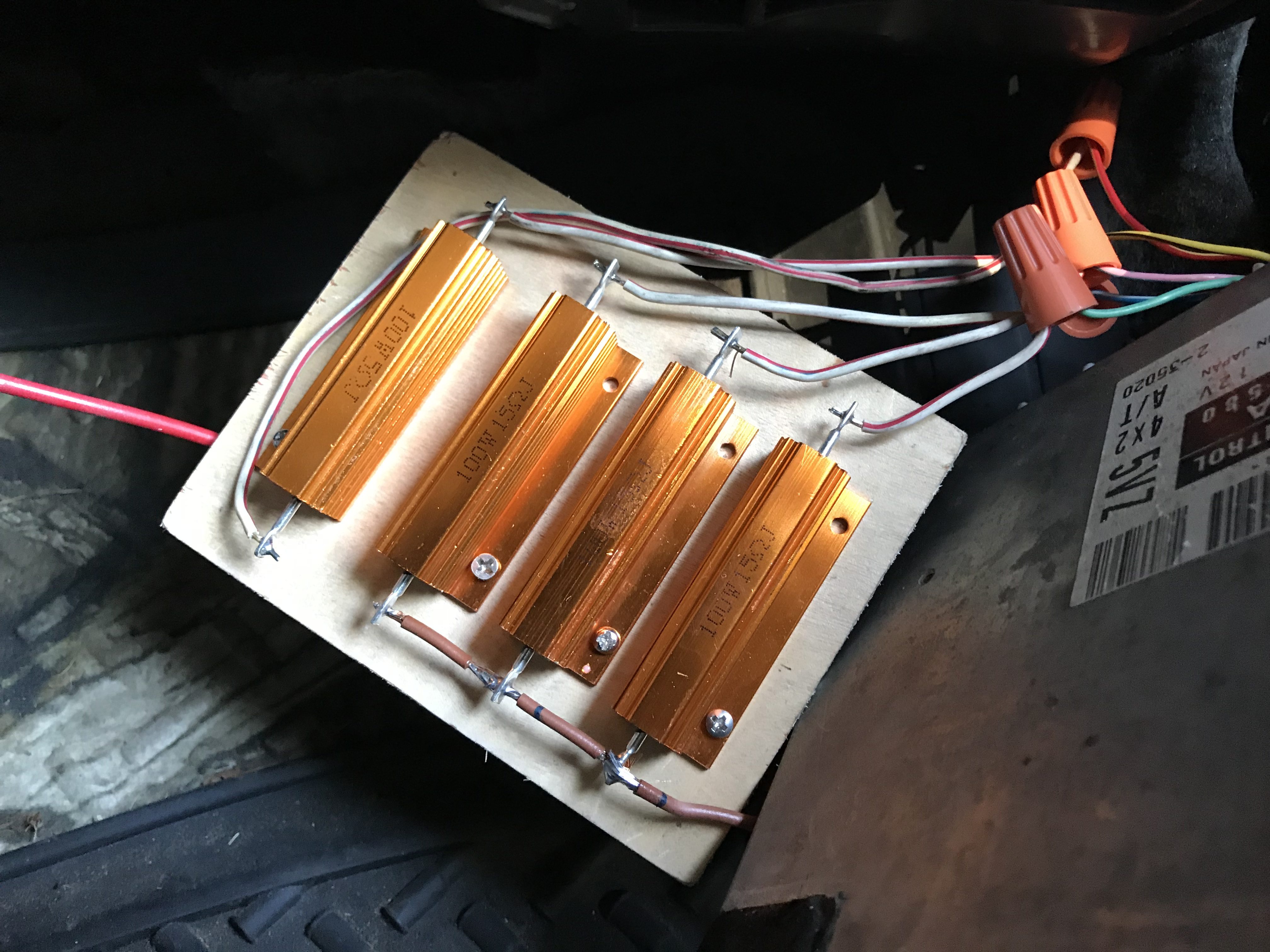
There are 2 options for the ground wire coming from 3 of the resistors:
- Run it directly to a bolt on the chassis for a direct ground
- Splice it into the ground wire coming from the ECU
I opted for option 2 to keep everything ECU-related contained and not have another ground point to worry about.
Testing
Once everything is wired up and the simulator is connected to the ECU and properly grounded, then the ECU should no longer through a Diagnostic Trouble Code (DTC) related to the automatic transmission solenoids. You may need an OBD-II port connected to your ECU to verify this, but if this was the only issue causing the check engine light to illuminate, then the check engine light should no longer be on!
Cost
This was a pretty cheap fix. I only needed to buy the power resistors, and was able to use wires and hardware I already had on hand.
- 15 ohm power resistors: $15.60
- 5 ohm power resistor: $7.70
- Scrap wires: free
- Wood mounting plate: free
- Wire nuts: free
Total cost: $23.30
I’m planning to revisit this mod in the near future to tidy it up and move it to the engine bay. The resistors still get pretty toasty, so I’ve slipped the whole assembly into an old coffee can that sits on the passenger floorboard for now so my wife doesn’t burn her foot!